Variable power optical system and imaging device
a technology of optical system and imaging device, applied in the field of variable power optical system, can solve the problems of plastic optical material susceptible to environmental change, the production cost of plastic optical material will come to about one-third of the production cost of a glass spherical lens, and the imaging performance of the lens system is induced
- Summary
- Abstract
- Description
- Claims
- Application Information
AI Technical Summary
Benefits of technology
Problems solved by technology
Method used
Image
Examples
example 1
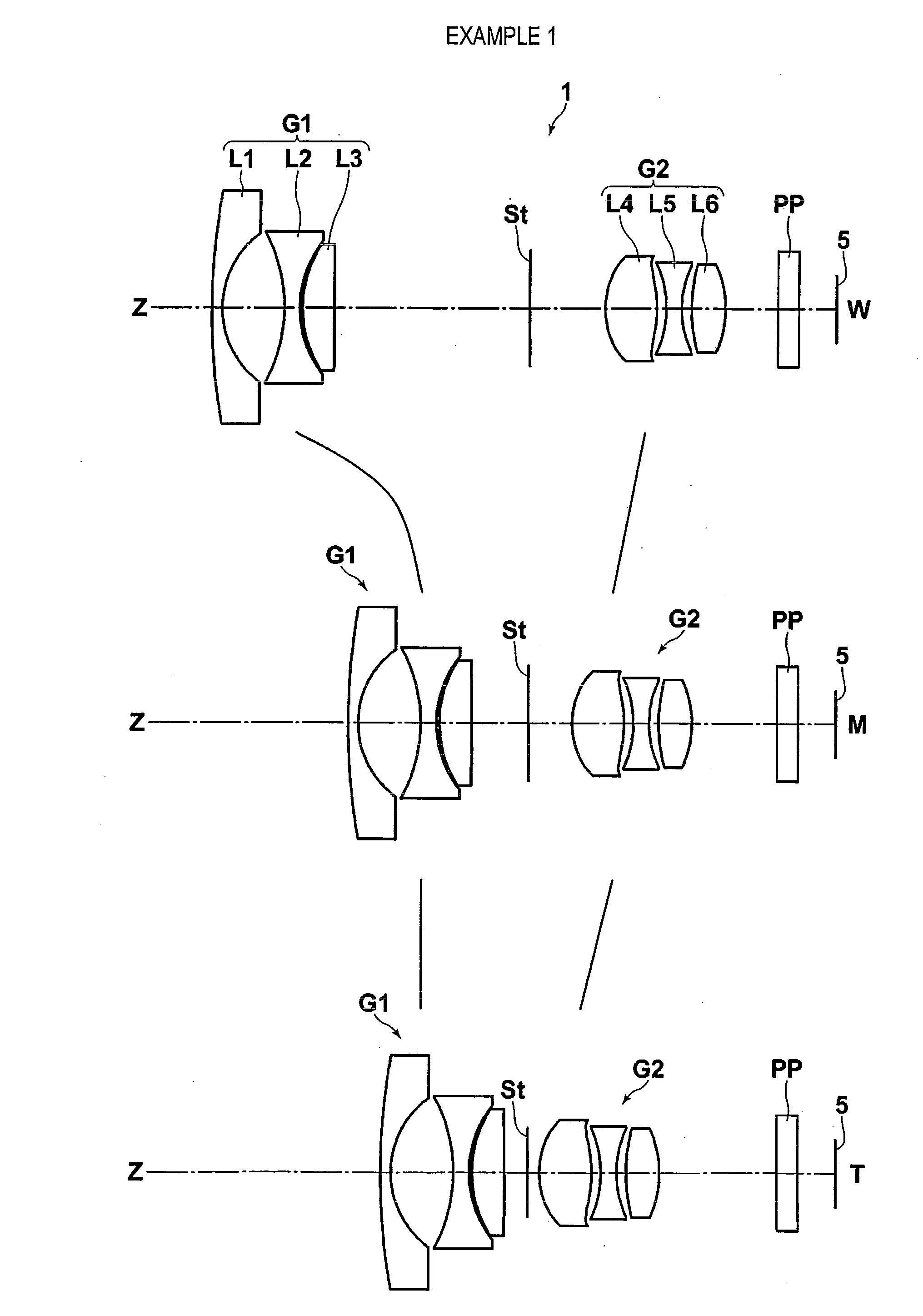
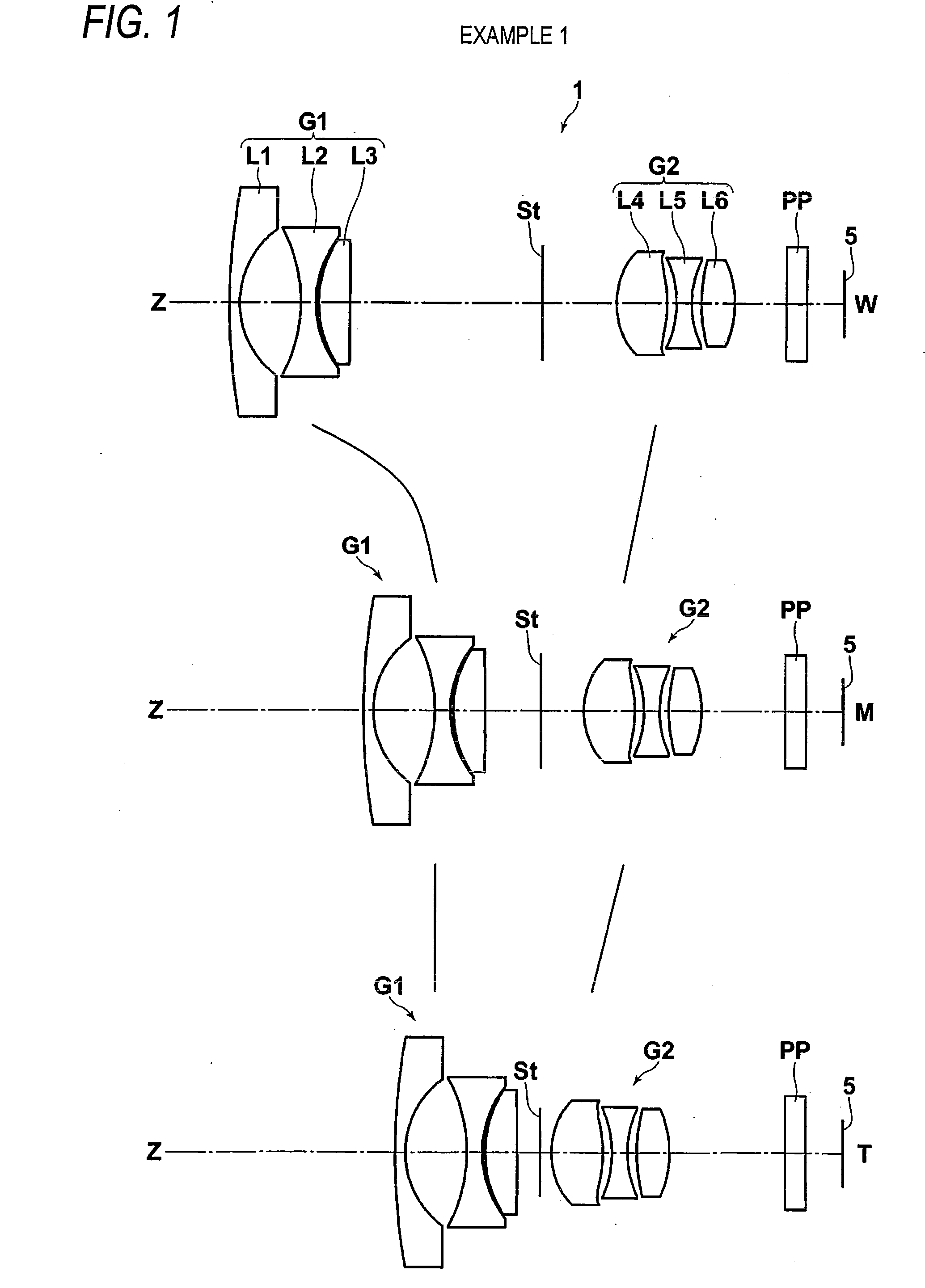
[0058]FIG. 1 shows cross sectional profiles of lenses in a variable power optical system of Example 1. Table 1 shows lens data pertaining to the variable power optical system of Example 1; Table 2 shows aspherical data; Table 3 shows various sets of data; and Table 4 shows data pertaining to temperature changes. Likewise, Tables 5 to 32 show lens data, aspherical data, various sets of data, temperature change data pertaining to variable power optical systems of Examples 2 to 8. Meanings of symbols in the tables are hereunder described by means of taking Example 1 as an example. The same also basically applies to the tables for Examples 2 through 8.
[0059]In relation to the lens data shown in Table 1, a surface number sequentially increases toward the image side while a surface of a constituent element closest to the object side is taken as the first surface, and on-axis surface spacing designates surface spacing between a surface of interest and the next surface along the optical axi...
example 2
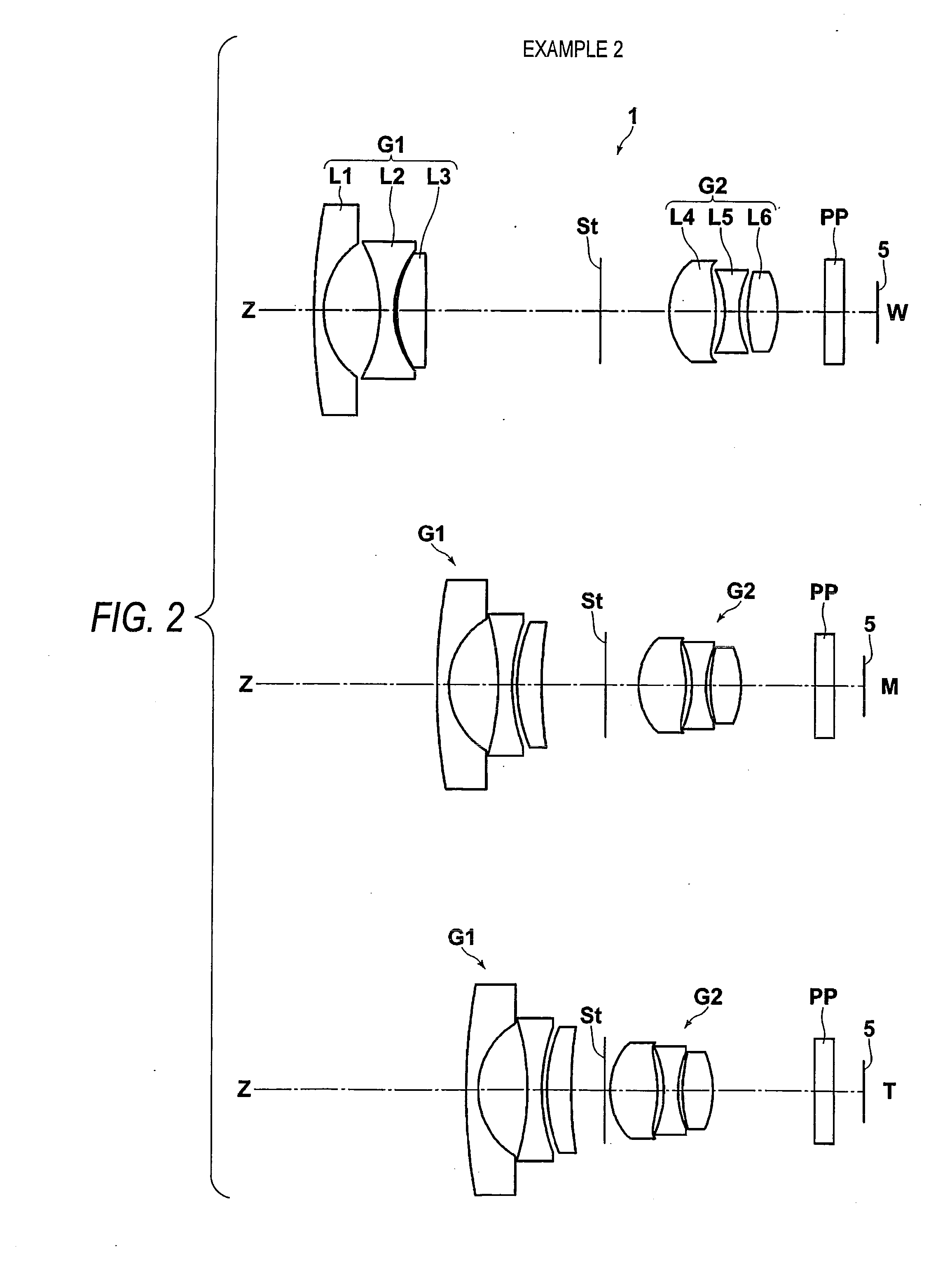
[0069]Table 5 shows lens data pertaining to a variable power optical system of Example 2; Table 6 shows aspherical data; Table 7 shows various data; and Table 8 shows temperature change data. FIG. 2 shows the configuration diagram of a lens (rough paths of movements of respective lens groups are omitted).
[0070]In Example 2, three plastic lenses L2, L4, and L5 are used. An aspherical lens is used for L4. Amounts of displacements of the imaging point obtained through calculation fall within an allowable range in response to a required temperature change of ±35° C., and the field angle achieved at the wide angle end is 126°. Thus, the objective of the invention is accomplished.
TABLE 5Example 2Lens dataSurfaceCurvature radiusSurface spacingNdνd161.4821.2821.8040046.628.0635.3141.000003−24.4601.5001.5095956.2418.9730.5341.00000516.5452.6031.9228518.9643.864D6(Variable)1.000007StopD7(Variable)1.00000 8*7.2844.9881.5095956.2 9*−10.9360.6581.0000010 −10.7381.5001.6059526.911 9.9730.4901.000...
example 3
[0071]Table 9 shows lens data pertaining to a variable power optical system of Example 3; Table 10 shows aspherical data; Table 11 shows various data; and Table 12 shows temperature change data. FIG. 3 shows the configuration diagram of a lens (rough paths of movements of respective lens groups are omitted).
[0072]In Example 3, three plastic lenses L2, L4, and L5 are used. An aspherical lens is used for L4. Amounts of displacements of the imaging point obtained through calculation fall within an allowable range in response to a required temperature change of ±35° C., and the field angle achieved at the wide angle end is 121°. Thus, the objective of the invention is accomplished.
TABLE 9Example 3Lens dataSurfaceCurvature radiusSurface spacingNdνd130.6241.2821.8040046.627.5595.2981.000003−22.2701.5011.5095956.2414.8290.8021.00000514.7122.6031.9228518.9633.216D6(Variable)1.000007StopD7(Variable)1.00000 8*7.4574.9201.5095956.2 9*−10.2201.3151.0000010 −12.3651.5001.6059526.911 7.7000.8901,...
PUM
 Abstract
Description
Claims
Application Information
 - R&D Engineer
- R&D Manager
- IP Professional
- Industry Leading Data Capabilities
- Powerful AI technology
- Patent DNA Extraction
Browse by: Latest US Patents, China's latest patents, Technical Efficacy Thesaurus, Application Domain, Technology Topic, Popular Technical Reports.
© 2024 PatSnap. All rights reserved.Legal|Privacy policy|Modern Slavery Act Transparency Statement|Sitemap|About US| Contact US: help@patsnap.com


