Power source apparatus for display and image display apparatus
a technology of power source apparatus and display screen, which is applied in the direction of static indicating device, liquid/fluent solid measurement, instruments, etc., can solve the problems of streak display defects on the screen, inability to achieve low power consumption, and more noticeable afterimage problems, so as to prevent the occurrence of afterimages and prevent the latch-up phenomenon. , the effect of low power consumption
- Summary
- Abstract
- Description
- Claims
- Application Information
AI Technical Summary
Benefits of technology
Problems solved by technology
Method used
Image
Examples
embodiment 1
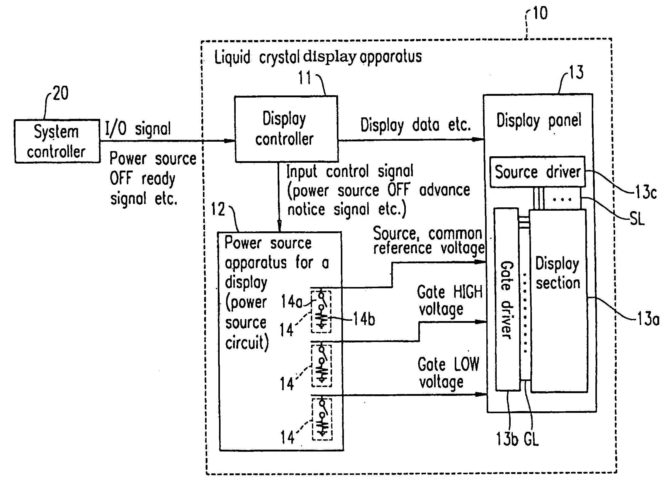
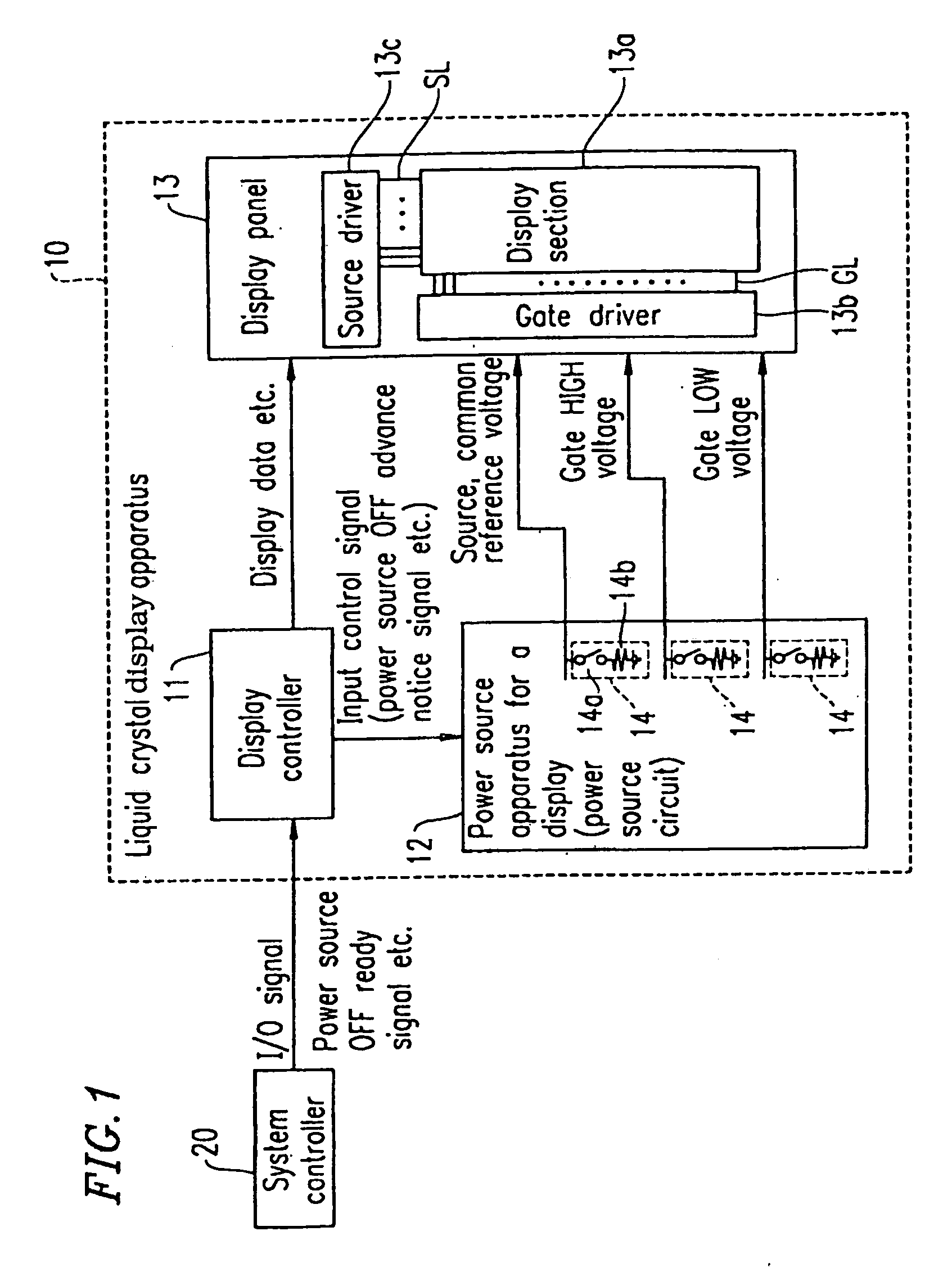
[0072]FIG. 1 is a block diagram showing a liquid crystal display apparatus according to Embodiment 1 of the present invention.
[0073]Referring to FIG. 1, a liquid crystal display apparatus 10 comprises a display controller 11, a power source circuit 12 (power source apparatus for a display), and a display panel 13 having a display section 13a.
[0074]The display controller 11 receives I / O (Input / Output) signals, a power source OFF ready signal and the like output from an external system controller 20 and outputs various signals, such as display data and the like, to the display panel 13 as well as a power source OFF advance notice signal (input control signal) to a power source circuit 12.
[0075]The power source circuit 12 receives a power source OFF advance notice signal and the like from the display controller 11. The power source circuit 12 has a discharge circuit 14 comprising a FET-SW (switching means comprising a FET transistor) 14a which transitions the ON state to the OFF state...
embodiment 2
[0096]In Embodiment 2, based on a power source OFF ready signal output from the system controller 20, 0 (V) or any constant voltage is applied as a pixel voltage to each pixel in the display panel 13 (mask writing).
[0097]FIG. 7 is a timing chart of signal voltages applied to a display panel 13 of a liquid crystal display apparatus according to Embodiment 2 of the present invention. The signal voltages are applied to the display panel 13 when 0 (V) or any constant voltage is applied as a pixel voltage to each pixel in the display panel 13 (mask writing). FIG. 15 is a block diagram schematically showing a configuration of a liquid crystal display apparatus 10A according to Embodiment 2 of the present invention. Members having substantially the same action and effect as those of FIG. 1 are referenced by the same numerals.
[0098]Referring to FIG. 7, 0 (V) or any constant voltage is applied as a pixel voltage to each pixel in the display panel 13 (mask writing) based on a power source OFF...
embodiment 3
[0106]In Embodiment 3, electric charges remaining in pixels are sufficiently discharged by controlling the mask writing time period and the gate voltage HIGH time period as in Embodiment 2 so that afterimages are overcome. In addition, a resistor element (the resistor element in the Related Art section) is used instead of the FET-SW 14a of Embodiment 1 and 2. FIG. 16 is a block diagram schematically showing a configuration of a liquid crystal display apparatus 10B according to Embodiment 3 of the present invention. Members having substantially the same action and effect as those of FIG. 1 are referenced by the same numerals.
[0107]A display controller 11B performs mask writing by applying a pixel voltage of 0 (V) or a predetermined value to each pixel for one horizontal time period or more based on a predetermined power source OFF ready signal from the system controller 20. Thereafter, the power source supply from the power source circuit 12 to the power source display section 13a is...
PUM
 Abstract
Description
Claims
Application Information
 - R&D
- Intellectual Property
- Life Sciences
- Materials
- Tech Scout
- Unparalleled Data Quality
- Higher Quality Content
- 60% Fewer Hallucinations
Browse by: Latest US Patents, China's latest patents, Technical Efficacy Thesaurus, Application Domain, Technology Topic, Popular Technical Reports.
© 2025 PatSnap. All rights reserved.Legal|Privacy policy|Modern Slavery Act Transparency Statement|Sitemap|About US| Contact US: help@patsnap.com


