
Infrared sensor and method of fabricating the same

a technology of infrared sensor and manufacturing method, which is applied in the field of infrared sensor, can solve the problems of inefficient use of sensor portion, sensor may have deterioration characteristics, and sensor resistance may be too grea

Inactive Publication Date: 2010-06-24
ELECTRONICS & TELECOMM RES INST
View PDF4 Cites 13 Cited by
  • Summary
  • Abstract
  • Description
  • Claims
  • Application Information

AI Technical Summary

Benefits of technology

[0023]The opening may be formed as small as possible within a range enabling patterning using lithography on the minimum distance between the sensing electrodes.

Problems solved by technology

In the case of the amorphous silicon-based material, its resistivity is great, and thus when electrodes are simply arranged in parallel, a resistance of the sensor may be too great.
As a result, the sensor may have deteriorated characteristics due to Johnson noise caused by the great resistance.
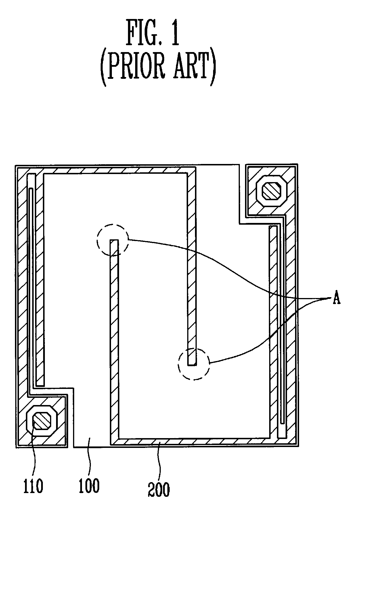
However, when the interdigitated electrode 200 is used, there is an inefficiently used portion in a sensing layer 100, and the volume of the sensing layer 100 is inefficiently used.
Therefore, there is much room to increase the noise.
Moreover, there is a cusp A vulnerable to the shape of the electrode 200, and non-uniform current around this portion causes 1 / f noise to be increased.

Method used


Image

  • Infrared sensor and method of fabricating the same
  • Infrared sensor and method of fabricating the same
  • Infrared sensor and method of fabricating the same

Examples


Embodiment Construction

[0029]The present invention will be described more fully hereinafter with reference to the accompanying drawings, in which exemplary embodiments of the invention are shown. This invention may, however, be embodied in different forms and should not be construed as limited to the embodiments set forth herein.

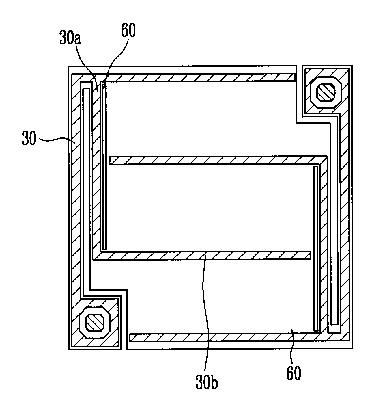
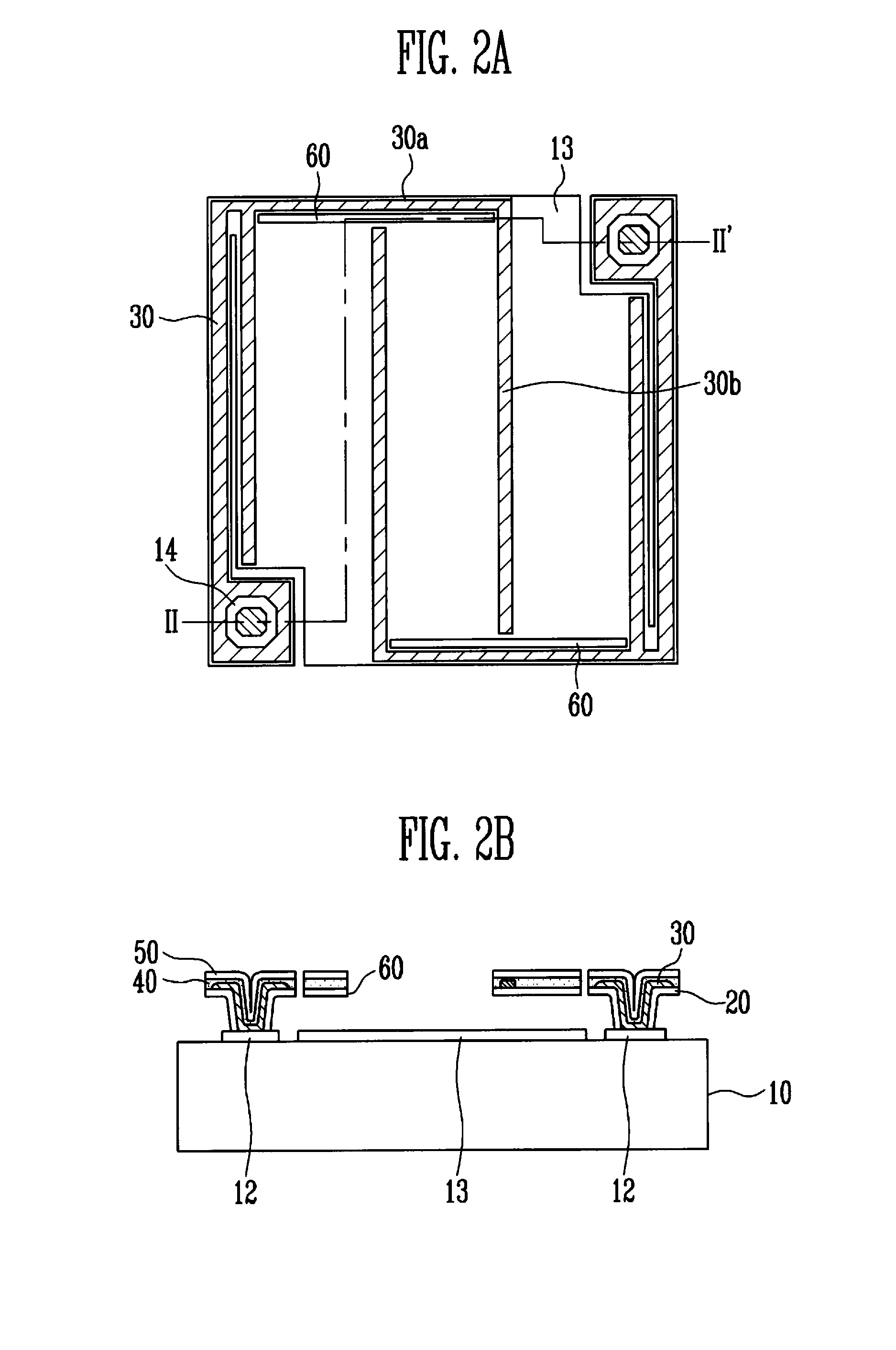
[0030]FIG. 2A is a plan view of an infrared sensor according to an exemplary embodiment of the present invention, and FIG. 2B is a cross-sectional view taken along line II-II′ of FIG. 2A.

[0031]Referring to FIGS. 2A and 2B, the reflection layer 13 is formed on a substrate 10 on which a read-out integrated circuit (ROIC) is formed, and a pad electrode 12 connected to the ROIC of the substrate 10 is formed on the same layer as the reflection layer 13.

[0032]A lower protection layer 20, a sensing layer 40, and an upper protection layer 50 are sequentially stacked on the reflection layer 13 to be spaced a predetermined distance therefrom.

[0033]Such a stacked structure is bent at a porti...


PUM


Abstract

An infrared sensor and a method of fabricating the same are provided. The sensor includes a substrate including a reflection layer and a plurality of pad electrodes, an interdigitated sensing electrode connected to the pad electrode and formed to be spaced apart from the reflection layer by a predetermined distance and a sensing layer formed on the sensing electrode and having an opening exposing a portion in which an interdigitated region of the sensing electrode connected to one pad region is separated from the sensing electrode connected to the other pad electrode. Therefore, the sensor has an electrode in a very simple constitution, and a sensing layer divided into rectangular blocks, so that current that non-uniformly flows into the electrode can be removed. Accordingly, the sensor in which current of the sensing layer can be uniformly flown, and noise is lowered can be implemented.

Description

CROSS-REFERENCE TO RELATED APPLICATION[0001]This application claims priority to and the benefit of Korean Patent Application No. 10-2008-0131658, filed Dec. 22, 2008, the disclosure of which is incorporated herein by reference in its entirety.BACKGROUND[0002]1. Field of the Invention[0003]The present invention relates to an infrared sensor and a method of fabricating the same. More specifically, the present invention relates to an infrared sensor having a sensor structure in which noise characteristics are improved, and a method of fabricating the same.[0004]2. Discussion of Related Art[0005]Basically, an uncooled infrared sensor senses a change in temperature of a sensor by absorbing incident infrared rays. Uncooled infrared sensors are classified into a bolometer type, a pyroelectric type and a thermopile type depending on a method of sensing a change in temperature. The bolometer-type infrared sensor operates by sensing a change in resistance of a sensor resistor according to tem...

Claims


Application Information

Patent Timeline
Patent Type & Authority Applications(United States)
IPC IPC(8): H01L27/14B05D5/12H01L21/00
CPCG01J5/02G01J5/023H01L31/108G01J5/20H01L31/022408G01J5/10H01L31/101
Inventor CHO, SEONG MOKRYU, HO JUNYANG, WOO SEOKCHEON, SANG HOONYU, BYOUNG GONCHOI, CHANG AUCK
Owner ELECTRONICS & TELECOMM RES INST
Learn More