Driving with inverters with low switching losses
- Summary
- Abstract
- Description
- Claims
- Application Information
AI Technical Summary
Benefits of technology
Problems solved by technology
Method used
Image

Examples
Embodiment Construction
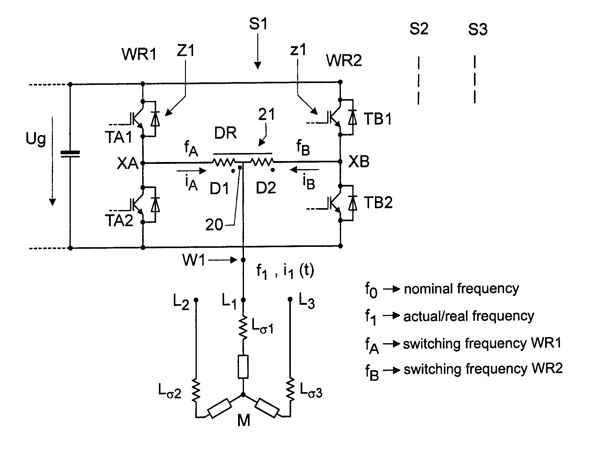
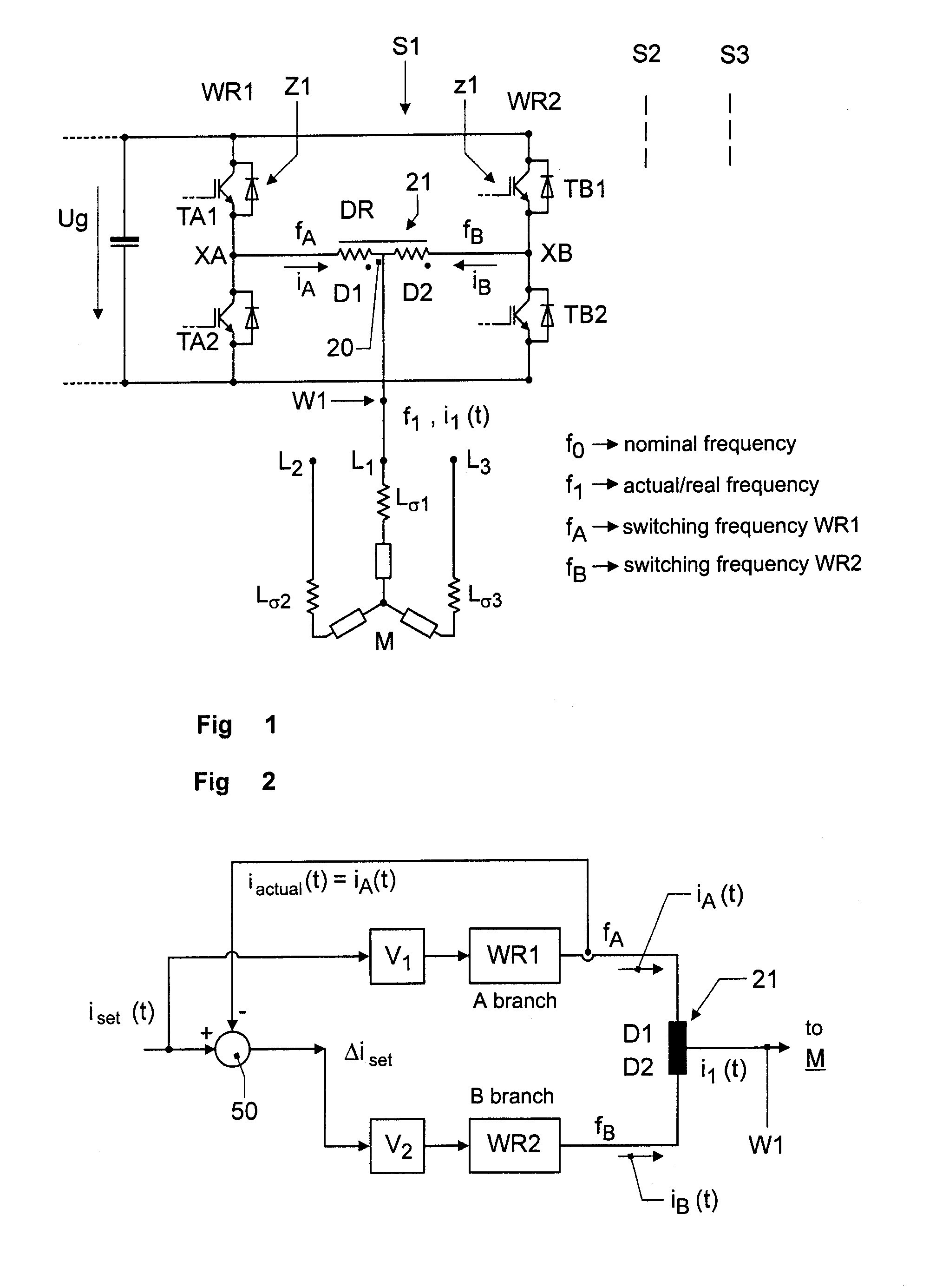
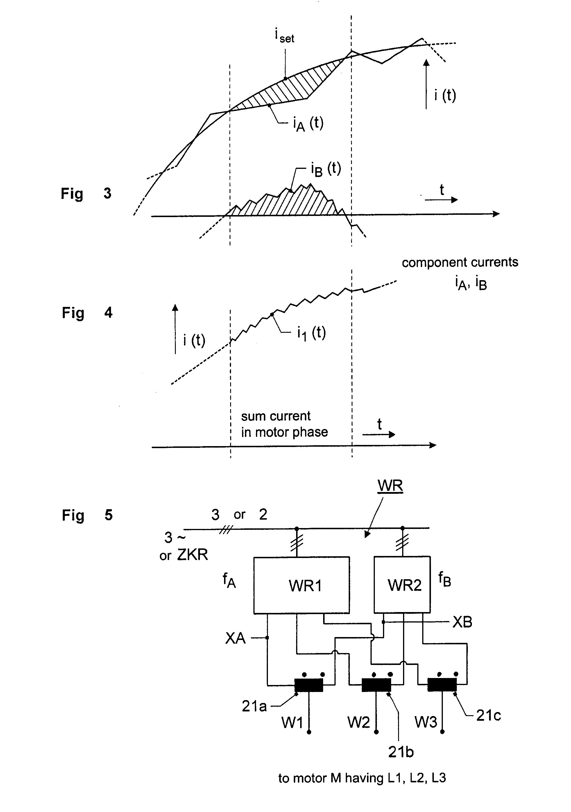
[0054]A synopsis of FIG. 5 and FIG. 1 gives an overview over the organization of the pulse inverters and the driving method, by means of which the symbolically illustrated machine M, in the embodiment a motor in form of a highly dynamic servo motor, is fed.
[0055]The machine is to be understood in the sense of a motor or generator and comprises three windings, which are either represented by windings L1, L2 and L3 or by the terminals (input terminals) thereof in the example illustrated in FIG. 1. Each winding symbolically has inductance and resistance. The motor M is connected, for example, in star.
[0056]A respective winding is supplied with a current i1 (t). The shown circuit arrangement of two inverters, i.e. an inverter for higher current values and with main power transmission, such as inverter WR1 shown in FIG. 5, and a second inverter WR2 for lower current values, but having a higher switching frequency, is to be described in such a way that initially an overview is given by me...
PUM
 Abstract
Description
Claims
Application Information
 - R&D
- Intellectual Property
- Life Sciences
- Materials
- Tech Scout
- Unparalleled Data Quality
- Higher Quality Content
- 60% Fewer Hallucinations
Browse by: Latest US Patents, China's latest patents, Technical Efficacy Thesaurus, Application Domain, Technology Topic, Popular Technical Reports.
© 2025 PatSnap. All rights reserved.Legal|Privacy policy|Modern Slavery Act Transparency Statement|Sitemap|About US| Contact US: help@patsnap.com