
Optical fiber manufacturing apparatus and optical fiber manufacturing method

a technology of optical fiber and manufacturing method, which is applied in the direction of glass fiber drawing apparatus, glass making apparatus, manufacturing tools, etc., can solve the problems of easy folding by an external force, carbon sheet, and difficult to completely prevent it from being destroyed, so as to maintain the sealing ability of the seal member, suppress the damage to the seal member, and improve the degree of freedom of deformation

Active Publication Date: 2010-06-10
THE FUJIKURA CABLE WORKS LTD
View PDF3 Cites 5 Cited by
  • Summary
  • Abstract
  • Description
  • Claims
  • Application Information

AI Technical Summary

Benefits of technology

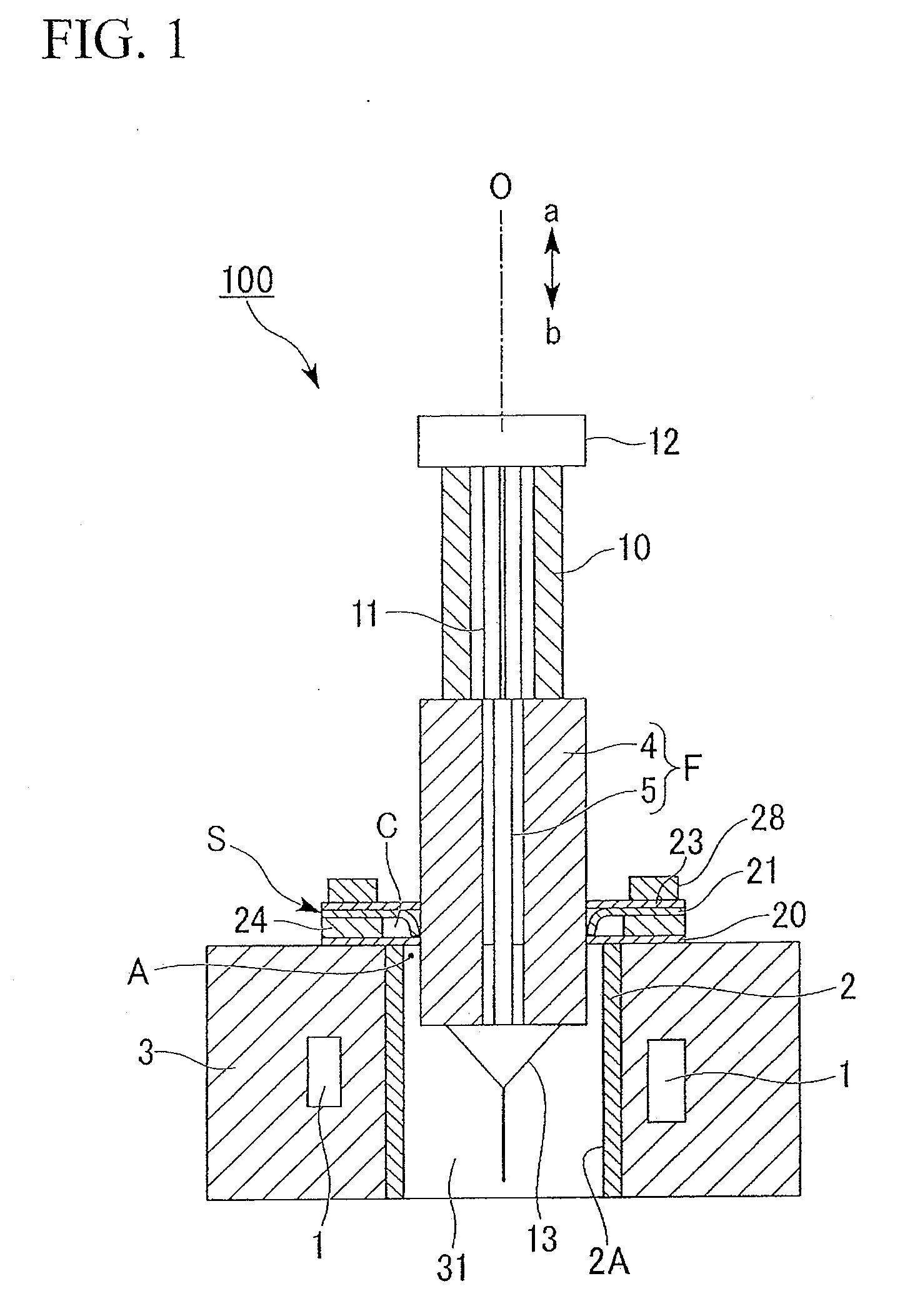
[0026]The present invention is contrived in view of the above-mentioned circumstances, and has an object of providing an optical fiber manufacturing apparatus and an optical fiber manufacturing method, (1) which cannot cause a gap between the optical fiber preform and the muffle tube to maintain the satisfactory sealing ability even when a difference in outer diameter exists between the optical fiber silica glass tube and a dummy silica tube and (2) which can maintain the excellent sealing ability at which the optical fiber perform is inserted and thus suppress the oxygen concentration in the drawing furnace to be lower than a target value (the oxygen concentration at an end of an inner space of the drawing furnace close to a seal member is 200 ppm or less) to stabilize the fiber diameter even when the outer diameter of the optical fiber preform varies with the drawing. That is, an object of the present invention is to provide an optical fiber manufacturing apparatus and an optical fiber manufacturing method, which need not use the conventional weight for maintaining the sealing ability and cannot cause problems relating to the damage of the optical fiber preform (Patent Document 2), problems relating to the poor bonding between the seal ring pieces and the generation of dust (Patent Document 3), or problems relating to the poor workability due to the generation of a large amount of powders (Patent Document 4).
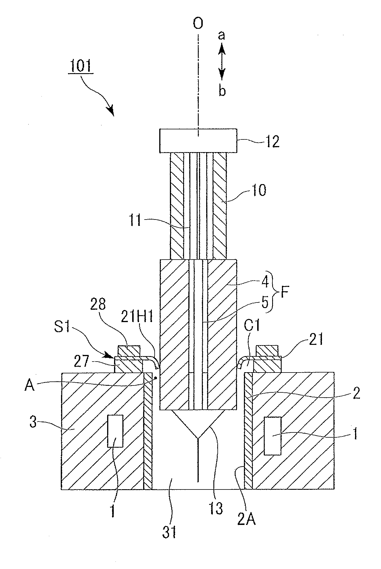
[0045]According to the optical fiber manufacturing apparatus and the optical fiber manufacturing method described above, since the first seal member which is disposed at the end of the drawing furnace and has the plural inner-circumference slits and the plural outer-circumference slits to enhance the degree of freedom in deformation is used, it is possible to suppress the damage to the seal member and to maintain the sealing ability of the seal member for sealing the periphery of the optical fiber preform.
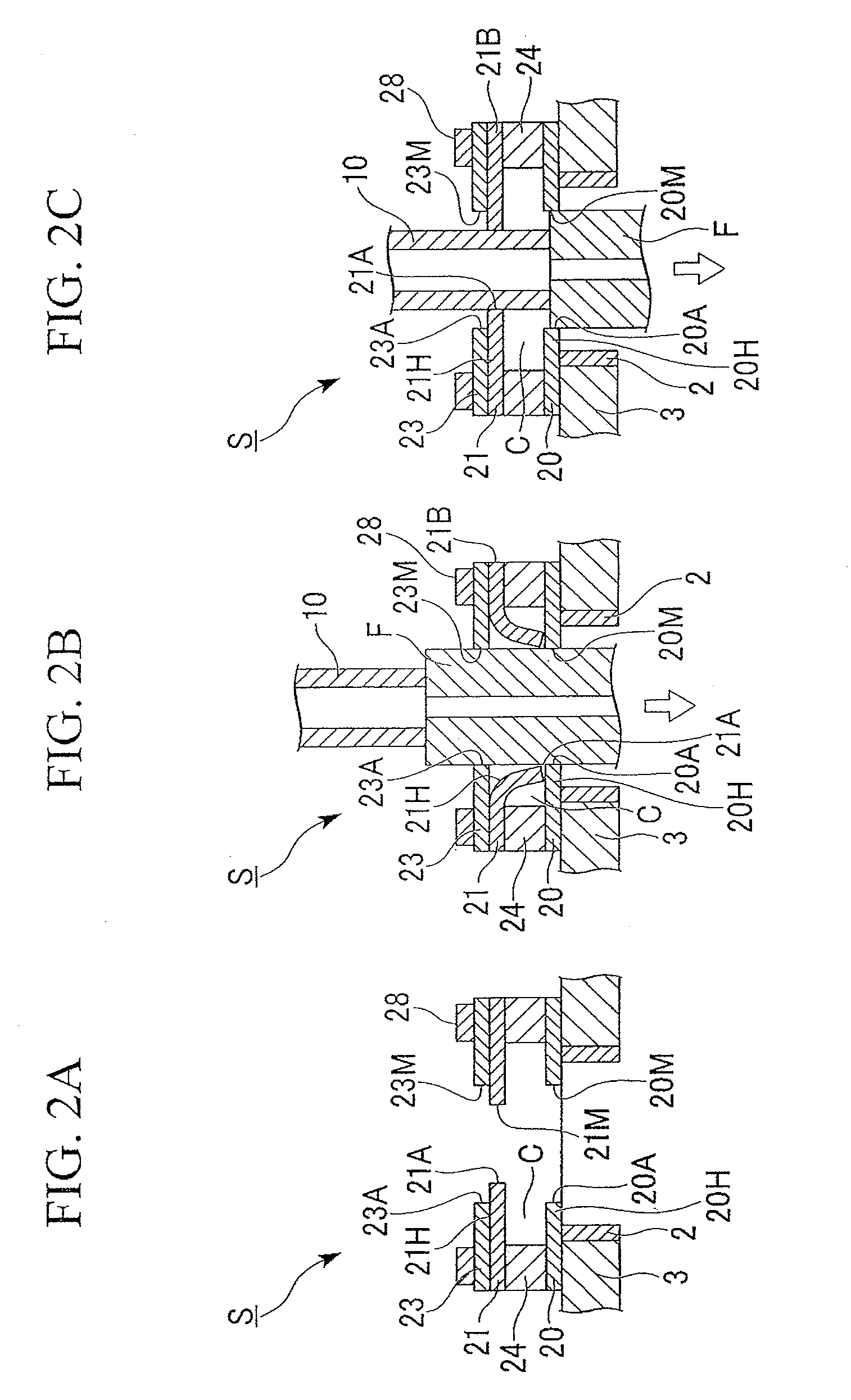
[0046]It is possible to bring the ends of the seal pieces between the inner-circumference slits (i.e., the inner circumferential edge of the slit-formed seal member) into close contact with the optical fiber preform by the deformation of the slit-formed seal member. In addition, even when the outer diameter of the optical fiber preform varies during the drawing of the optical fiber or when a difference in outer diameter exists between the optical-fiber silica glass tube and the dummy silica tube, it is possible to maintain the excellent sealing ability between the optical fiber preform and the muffle tube without causing a gap between the optical fiber preform and the muffle tube. Accordingly, it is possible to prevent ambient air from intruding and to easily suppress the oxygen concentration in the drawing furnace to be equal to or less than a target value (for example, the oxygen concentration in the end of the inner space of the drawing furnace close to the seal member is 200 ppm or less). As a result, it is possible to stabilize the diameter of the drawn fiber and to accomplish the prevention of degradation and the extension of the lifetime of the muffle tube or the heater formed of carbon in the drawing furnace.

Problems solved by technology

However, as described above, since the carbon sheet is very brittle, it is easily folded by an external force.
When the thickness of the carbon sheet is thin, the carbon sheet can be flexible, but hard to completely prevent it from being destroyed.

Method used


Image

  • Optical fiber manufacturing apparatus and optical fiber manufacturing method
  • Optical fiber manufacturing apparatus and optical fiber manufacturing method
  • Optical fiber manufacturing apparatus and optical fiber manufacturing method

Examples


example 1

[0116]A dummy silica tube 10 with an outer diameter of φ145 mm, an inner diameter of φ80 mm, and a length of 800 mm was jointed by an H2 / O2 burner to an end of an optical-fiber silica glass tube 4 with an outer diameter of φ155 mm, an inner diameter of φ45 mm, and a length of 1500 mm.

[0117]A dummy member 13 (with a length of 100 mm) serving as an outlet portion at the time of drawing a fiber was jointed by an H2 / O2 burner to the other end of the optical-fiber silica glass tube 4.

[0118]The optical-fiber silica glass tube 4, the dummy silica tube 10, and the dummy member 13 which had been jointed together were cleaned with hydrofluoric acid, rinsed with pure water, and then dried. The inner face of the dried optical-fiber silica glass tube 4 was lit with a halogen lamp and observed. As a result, no defects and no dry spots (water marks) were observed.

[0119]Thereafter, a fluorine-resin protective jig (not shown in the figures) from which static electricity was removed in advance was in...

example 2

[0123]A dummy silica tube 10 with an outer diameter of φ180 mm, an inner diameter of φ100 mm, and a length of 800 mm was jointed by an H2 / O2 burner to an end of an optical-fiber silica glass tube 4 with an outer diameter of φ190 mm, an inner diameter of φ55 mm, and a length of 1500 mm. An optical-fiber core rod 5 (with a size of φ52 mm×1500 mm, which is bent by a flame process) was inserted into the optical-fiber silica glass tube 4 to which the dummy silica tube 10 was jointed in the same way as Example 1. Three carbon sheets 20, 21, and 23 (with a thickness of 0.6 mm) were used as the seal members for sealing the gap between the muffle tube 2 and the optical fiber preform F.

[0124]The slit-less carbon sheets 20 and 23 (with an inner diameter of φ191 mm) having the shape shown in FIG. 3A were disposed on and under the slit-formed carbon sheet 21 (with an inner diameter of φ179.5 mm and 72 slits) having the shape shown in FIG. 3B so as to overlap the slit-formed carbon sheet 21.

[0125...

example 3

[0126]The drawing was carried out by the same method as Example 1, except that the slit-formed carbon sheet 21 having the shape shown in FIG. 3B and having 36 slits in total was used.

[0127]Similarly to Example 1, the oxygen concentration just beneath the slit-formed carbon sheet 21 before the drawing was measured. As a result, it was confirmed that the oxygen concentration was 120 ppm, which is a sufficiently low value, and the sealing ability between the optical fiber preform F and the drawing furnace 3 was satisfactory.

[0128]Similarly to Example 1, the oxygen concentration during the drawing was measured. As shown FIG. 2B, when the optical-fiber silica glass tube 4 was inserted into the seal mechanism S, the oxygen concentration was in the range of 110 to 140 ppm. As shown in FIG. 2C, when the dummy silica tube 10 was inserted into the seal mechanism S, the oxygen concentration was in the range of 100 to 120 ppm. From this measurement result, it was confirmed that the sealing abil...


PUM

PropertyMeasurementUnit
Fractionaaaaaaaaaa
Diameteraaaaaaaaaa
Concentrationaaaaaaaaaa

Abstract

An optical fiber manufacturing apparatus for manufacturing an optical fiber by drawing a optical fiber preform, including: a drawing furnace having therein a muffle tube into which the optical fiber preform is inserted and heating the optical fiber preform; and a first seal member which is disposed at an insert side of the drawing furnace so as to be coaxial with the drawing furnace and which seals the optical fiber preform inserted into an opening formed at the center thereof, wherein the first seal member includes a plurality of inner-circumference slits formed in the inner circumference thereof and a plurality of outer-circumference slits formed in the outer circumference thereof.

Description

BACKGROUND OF THE INVENTION[0001]1. Field of the Invention[0002]The present invention relates to an optical fiber manufacturing apparatus and an optical fiber manufacturing method which can be suitably used in an optical fiber drawing process using a rod-in-tube method.[0003]Priority is claimed on Japanese Patent Application No. 2008-311219 filed Dec. 5, 2008, the contents of which are incorporated herein by reference.[0004]2. Description of the Related Art[0005]A method of sintering and vitrifying a porous silica preform produced by a soot method such as a VAD method or an OVD method is generally used in manufacturing an optical fiber. However, with the recent increase in size of the optical fiber preform, there is a need for a method with higher productivity.[0006]As such a method, a rod-in-tube method of manufacturing a cladding layer, which occupies most of an optical fiber, by the use of a jacket of an optical-fiber silica glass tube, is known. This method is roughly classified...

Claims


Application Information

Patent Timeline
IPC IPC(8): C03B37/02
CPCC03B2205/80C03B37/029
Inventor NUNOME, TOMOHIRO
Owner THE FUJIKURA CABLE WORKS LTD
Learn More