Estimating a time offset between stationary clocks

a time offset and stationary clock technology, applied in the field of time synchronization, can solve the problems of preventing or degrading gps reception, and no alternative implementations of time synchronization of stationary clocks are currently availabl

Active Publication Date: 2010-06-03
HITACHI ENERGY SWITZERLAND AG
View PDF4 Cites 17 Cited by
  • Summary
  • Abstract
  • Description
  • Claims
  • Application Information

AI Technical Summary

Problems solved by technology

However, it is known that propagation and interference problems may degrade or even prevent GPS reception.
While navigating vehicles may readily switch to other systems for determining their position, no such alternatives have been implemented today for the time synchronization of stationary clocks.

Method used


Image

  • Estimating a time offset between stationary clocks
  • Estimating a time offset between stationary clocks
  • Estimating a time offset between stationary clocks

Examples


Embodiment Construction

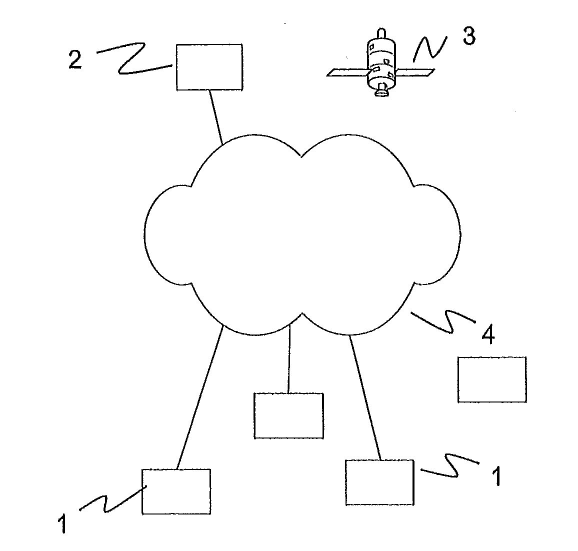
[0012]Exemplary embodiments are directed to time synchronization of two clocks, such as two (or more) stationary clocks.

[0013]According to the exemplary embodiments, a global time signal from a global time reference or time source in common view can be used to calculate a common view based clock offset between two stationary clocks instead of two respective clock offsets between each one of the clocks and the global time reference. In parallel, a network based clock offset between the two clocks can be calculated based on messages exchanged over a communication network interconnecting the two clocks and without reverting to the global time reference. For example, the two most recent values of the common view and network based clock offsets can then be combined or superposed in a seamless or hitless way to produce a final time offset estimate.

[0014]In an exemplary variant of the disclosure, the combination of the independently calculated common view and network based clock offsets is...


PUM


Abstract

Time synchronization of two clocks is disclosed herein, such as two stationary clocks. A global time signal from a global time reference or common time source can be used to calculate a common view based clock offset between the two clocks. In parallel, a network based clock offset between the two clocks can be calculated based on messages exchanged over a communication network interconnecting the two clocks, without reverting to the global time reference. Two recent values (e.g., the two most recent values) of the common view clock offset and the network based clock offset can be combined or superposed in a seamless way to produce a final time offset estimate. The combination of independently calculated common view and network based clock offsets can be a weighted average of the two values, involving respective weights based on quality estimates of the latter. The time synchronization schemes based on a Global Positioning System (GPS) and a wide area communication network can be combined to synchronize the stationary clocks of phasor measurement units (PMUs) of a wide area monitoring system to a central server clock at a Network Control Center (NCC) of the system.

Description

RELATED APPLICATIONS[0001]This application claims priority as a continuation application under 35 U.S.C. §120 to PCT / EP2008 / 057931, which was filed as an International Application on Jun. 23, 2008 designating the U.S., and which claims priority to European Application 07113845.7 filed in Europe on Aug. 6, 2007. The entire contents of these applications are hereby incorporated by reference in their entireties.FIELD[0002]The disclosure relates to the field of time synchronization between two geographically separated clocks, such as the stationary clocks of the phasor measurement units of a wide area monitoring system for a power transmission network.BACKGROUND INFORMATION[0003]For the wide area monitoring of power transmission networks, phasor measurement units (PMUs) are installed at distributed locations. The PMUs perform sampling of current and voltage waveforms, calculate phasor values from the sampled waveforms, and cyclically send the phasor values to a Network Control Center (N...

Claims


Application Information

Patent Timeline
Patent Type & Authority Applications(United States)
IPC IPC(8): G04G7/02G04G99/00
CPCH02J13/0017H04J3/0644Y02E60/7807Y04S10/527Y04S40/12H04J3/0682H02J13/00006Y02E60/00Y04S10/52
Inventor DZUNG, DACFEYLARSSON, MATS
Owner HITACHI ENERGY SWITZERLAND AG
Why Eureka
Try Eureka