
Constant-Mode Auto-Drill with Pressure Derivative Control

a technology of derivative control and constant-mode auto-drill, which is applied in the direction of survey, borehole/well accessories, artificial islands, etc., can solve the problems of time-consuming and substantial damage to existing structures or roadways, and achieve the effect of reducing the output of thrust pumps

Active Publication Date: 2010-06-03
VERMEER MFG CO
View PDF5 Cites 25 Cited by
  • Summary
  • Abstract
  • Description
  • Claims
  • Application Information

AI Technical Summary

Benefits of technology

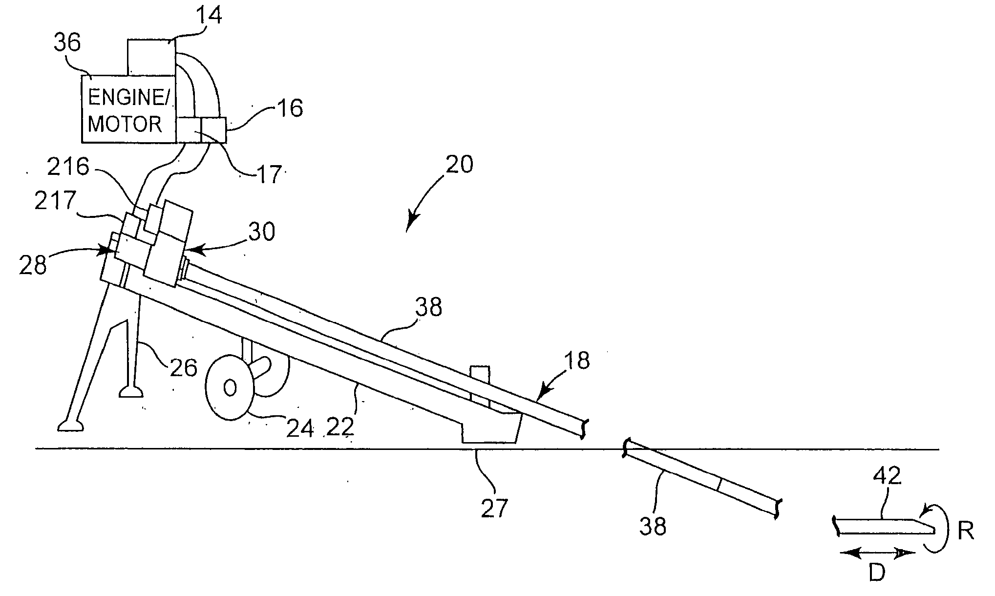
[0025]Some method embodiments of the invention concern HDD in an automatic drilling mode. Such method embodiments can include maintaining a constant output parameter while performing a drilling operation using an HDD rig having a thrust pump, generating hydraulic fluid pressure measurements from one or more pumps of the HDD rig, comparing the hydraulic fluid pressure measurements to a variable pressure limit, calculating a derivative value using the measured hydraulic fluid pressure measurements, comparing the derivative value to a derivative threshold, decreasing the variable pressure limit when the derivative value exceeds the derivative threshold, wherein the amount that the variable pressure limit is decreased is based on one or more of the hydraulic fluid pressure measurements, and reducing output of the thrust pump when the comparison of the hydraulic fluid pressure measurements to the variable pressure limit indicates that one or more of the hydraulic fluid pressure measurements exceed the variable pressure limit.
[0039]means for reducing output of the thrust pump when the comparison of the hydraulic fluid pressure measurements to the variable pressure limit indicates that one or more of the hydraulic fluid pressure measurements exceed the variable pressure limit.

Problems solved by technology

Trenching, however, can be time consuming and can cause substantial damage to existing structures or roadways.

Method used


Image

  • Constant-Mode Auto-Drill with Pressure Derivative Control
  • Constant-Mode Auto-Drill with Pressure Derivative Control
  • Constant-Mode Auto-Drill with Pressure Derivative Control

Examples


Embodiment Construction

Brief Description of the Drawings

[0043]The accompanying drawings, which are incorporated herein and constitute a part of the specification, illustrate several aspects of the invention and together with the description, serve to explain the principles of the invention. A brief description of the drawings is as follows:

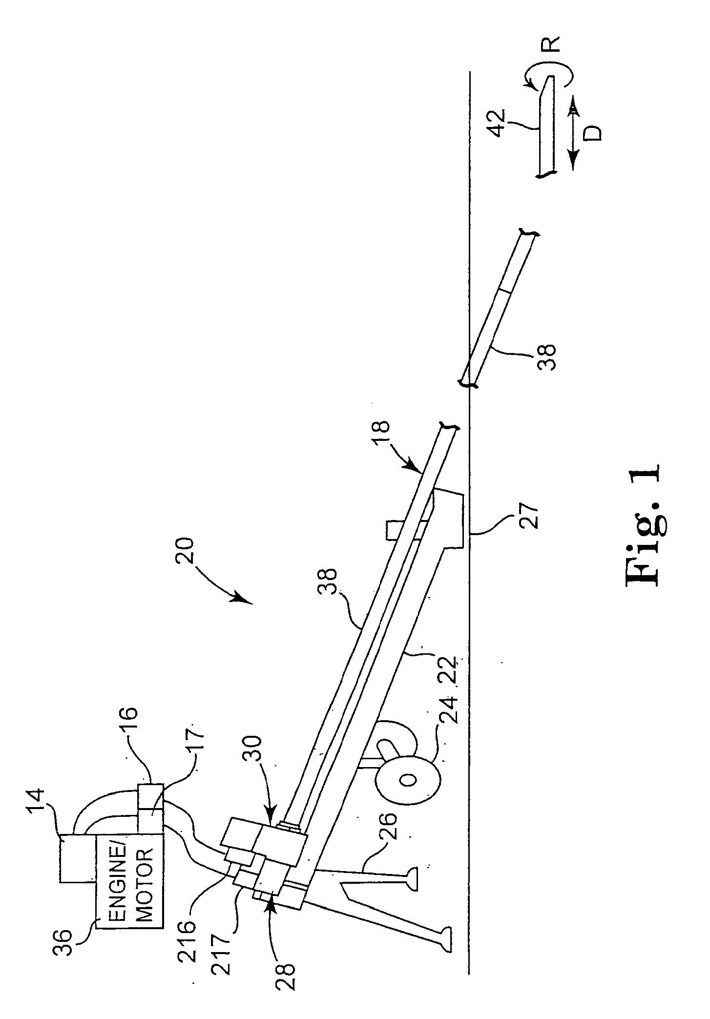
[0044]FIG. 1 illustrates a horizontal directional drilling machine;

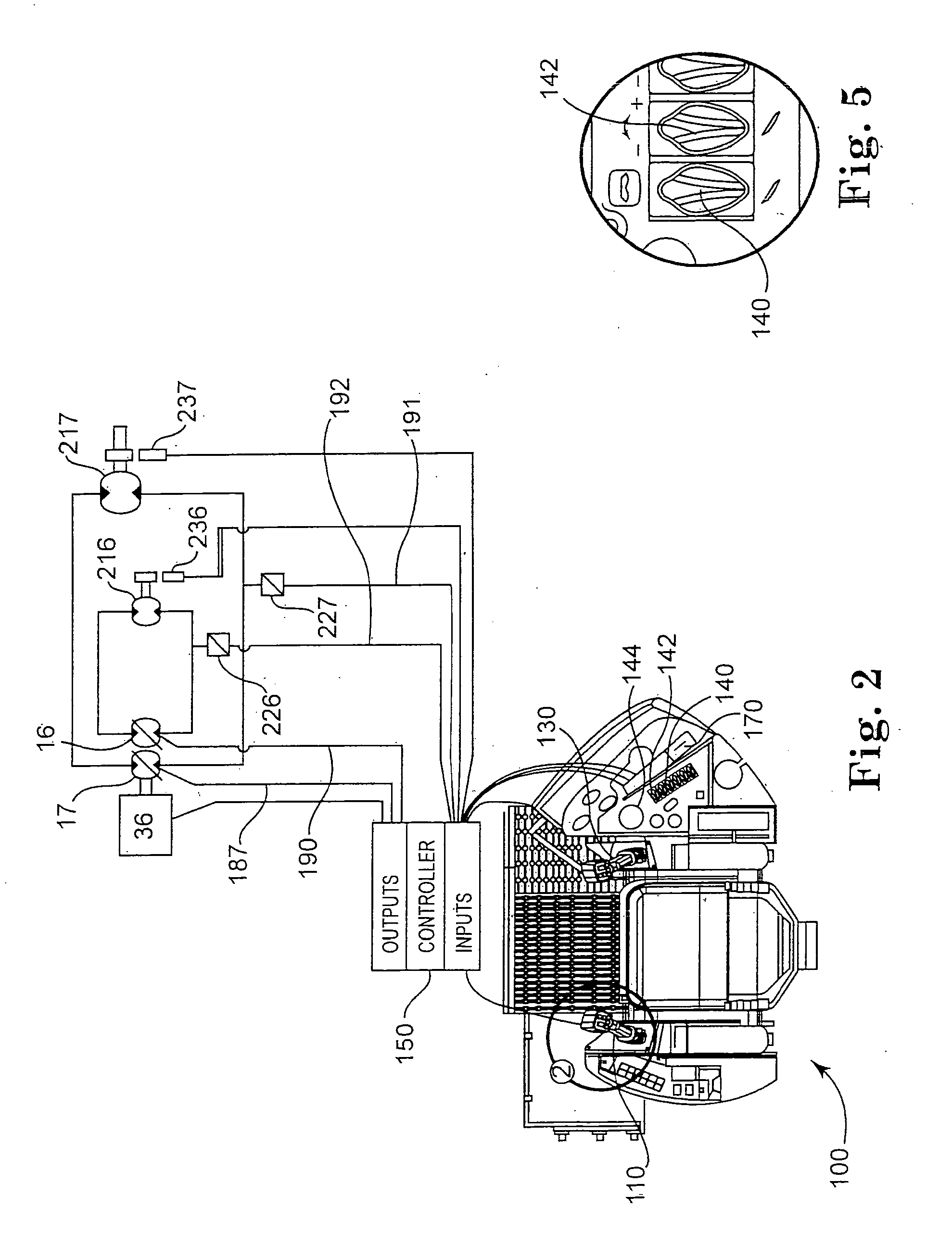
[0045]FIG. 2 illustrates the operator control station of a horizontal directional drilling machine according to the principles of the present invention;

[0046]FIG. 3 illustrates a control lever of the operator control station of FIG. 2;

[0047]FIG. 4 illustrates a label identifying the function of the controls found on the control lever of FIG. 3;

[0048]FIG. 5 illustrates controls found on the right side of the operator control station of FIG. 2;

[0049]FIG. 6 illustrates a display according to the principles of the present invention;

[0050]FIG. 7 illustrates the rates of increase of rotational movement and axi...


PUM


Abstract

Some embodiments of the invention concern HDD in an automatic drilling mode. Such embodiments can include maintaining a constant output parameter while performing a drilling operation using an HDD rig (20) having a thrust pump, generating hydraulic fluid pressure measurements from one or more pumps of the HDD rig, comparing the hydraulic fluid pressure measurements to a variable pressure limit, calculating a derivative value using the measured hydraulic fluid pressure measurements, comparing the derivative value to a derivative threshold, decreasing the variable pressure limit when the derivative value exceeds the derivative threshold, wherein the amount that the variable pressure limit is decreased is based on one or more of the hydraulic fluid pressure measurements, and reducing output of the thrust pump when the comparison of the hydraulic fluid pressure measurements to the variable pressure limit indicates that one or more of the hydraulic fluid pressure measurements exceed the variable pressure limit.

Description

FIELD OF THE INVENTION[0001]The present invention relates generally to underground boring machines and methods for controlling underground boring. More particularly, the present invention relates to underground boring machines for use in horizontal directional drilling and to an improved method of, and apparatus for, providing an automatic control mode for drilling using a pressure derivative.BACKGROUND OF THE INVENTION[0002]Utility lines for water, electricity, gas, telephone and cable television are often run underground for safety and aesthetics reasons, among others. Sometimes the underground utilities are buried in a trench that is then back filled. Trenching, however, can be time consuming and can cause substantial damage to existing structures or roadways. Consequently, horizontal directional drilling (“HDD”) is often used to avoid these drawbacks.[0003]A typical horizontal directional drilling machine includes a frame on which is mounted a rotational drive mechanism. The rot...

Claims


Application Information

Patent Timeline
Patent Type & Authority Applications(United States)
IPC IPC(8): E21B47/022
CPCE21B44/06E21B7/046
Inventor CARLSON, ROBIN W.LANE, PHILIP R.
Owner VERMEER MFG CO
Learn More