
Harmonic transposition

Active Publication Date: 2011-01-06
DOLBY INT AB
View PDF23 Cites 91 Cited by
  • Summary
  • Abstract
  • Description
  • Claims
  • Application Information

AI Technical Summary

Benefits of technology

[0010]The present invention relates to the problem of improved transient performance for harmonic transposition, as well as assorted improvements to known methods f

Problems solved by technology

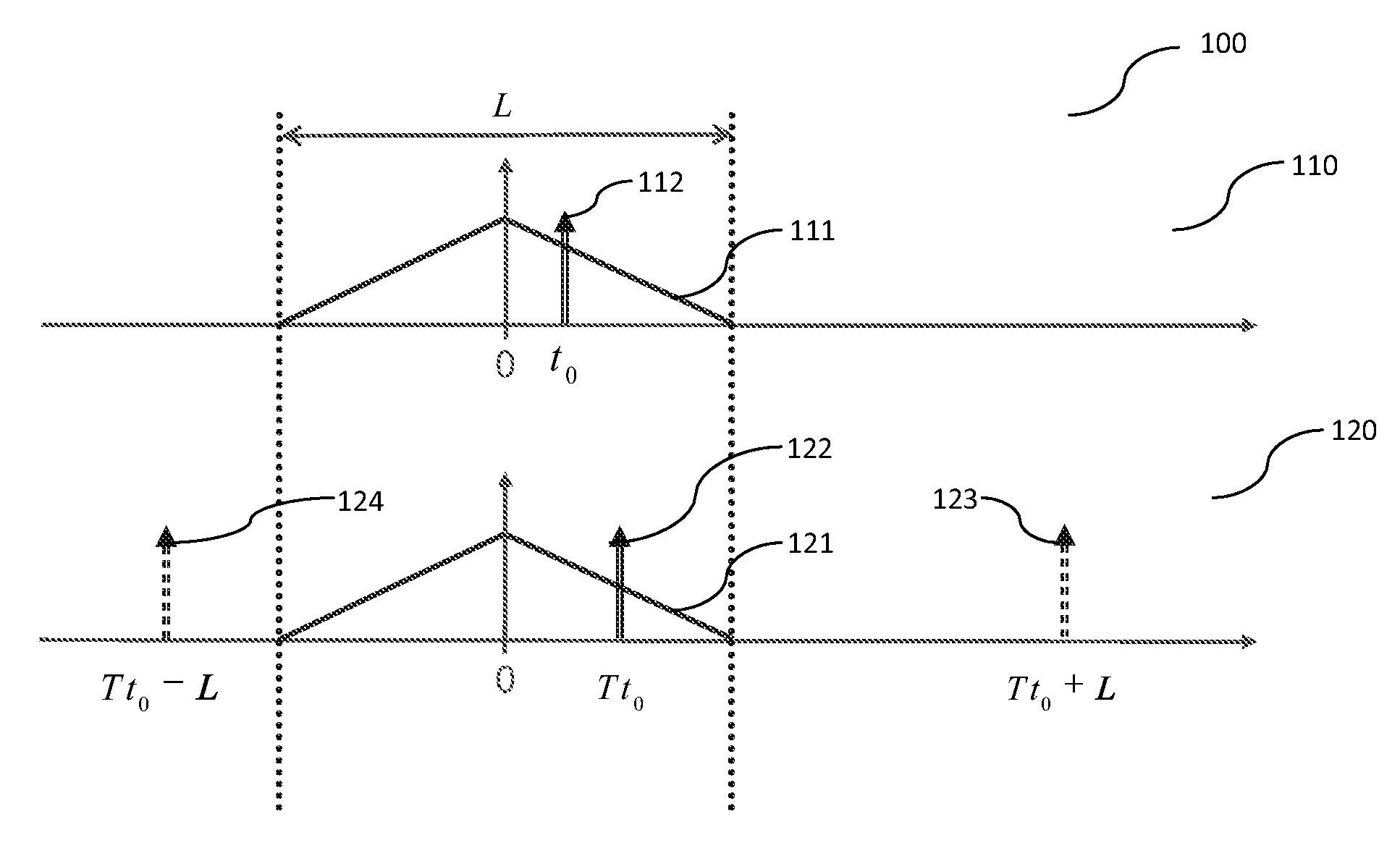
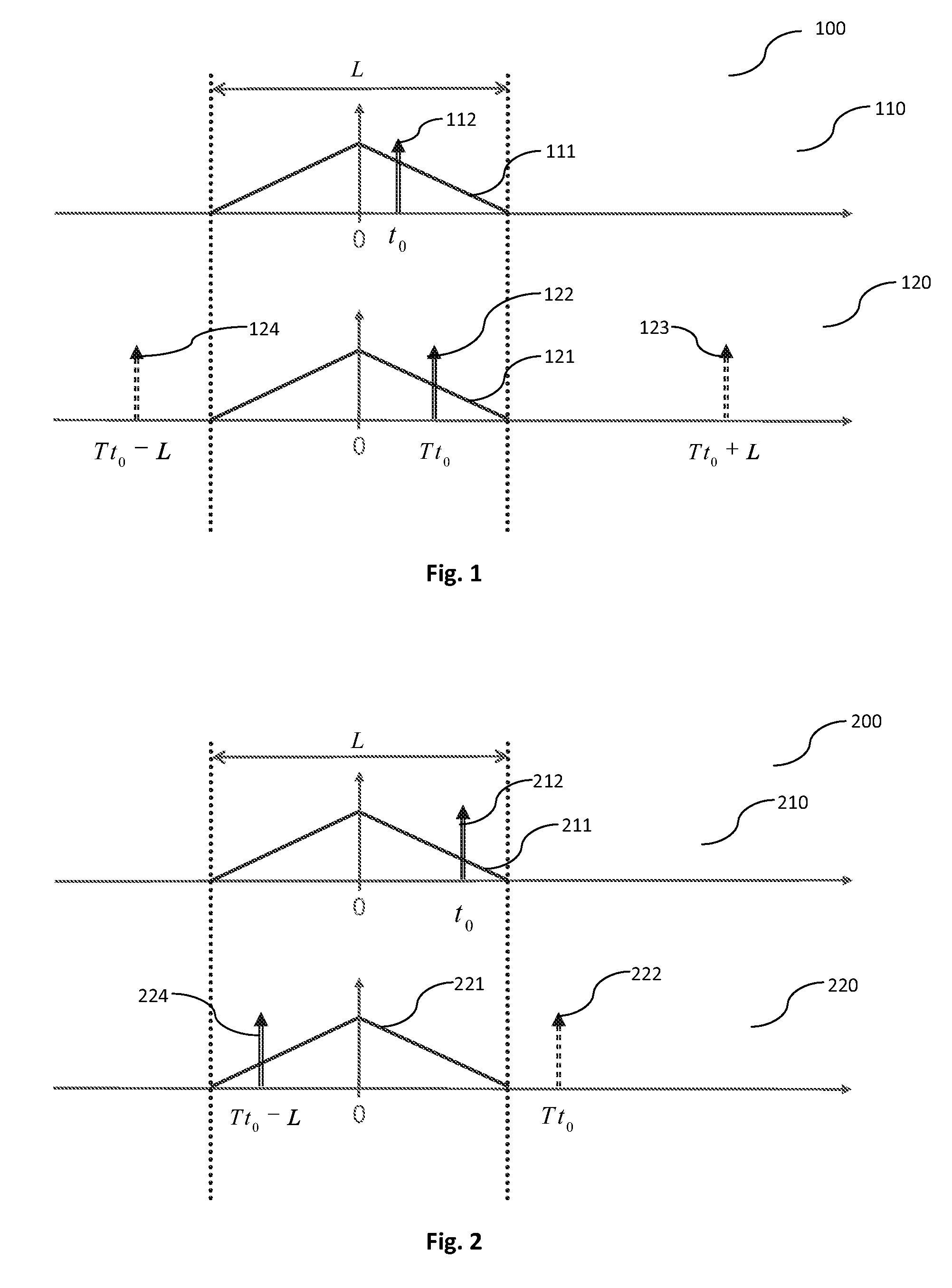
One of the underlying problems that exist with these methods are the opposing constraints of an intended high frequency resolution in order to get a high quality transposition for stationary sounds, and the time response of the system for transient or percussive sounds.
In other words, while the use of a high frequency resolution is beneficial for the transposition of stationary signals, such high frequency resolution typically requires lar

Method used


Image

  • Harmonic transposition
  • Harmonic transposition
  • Harmonic transposition

Examples


first embodiment

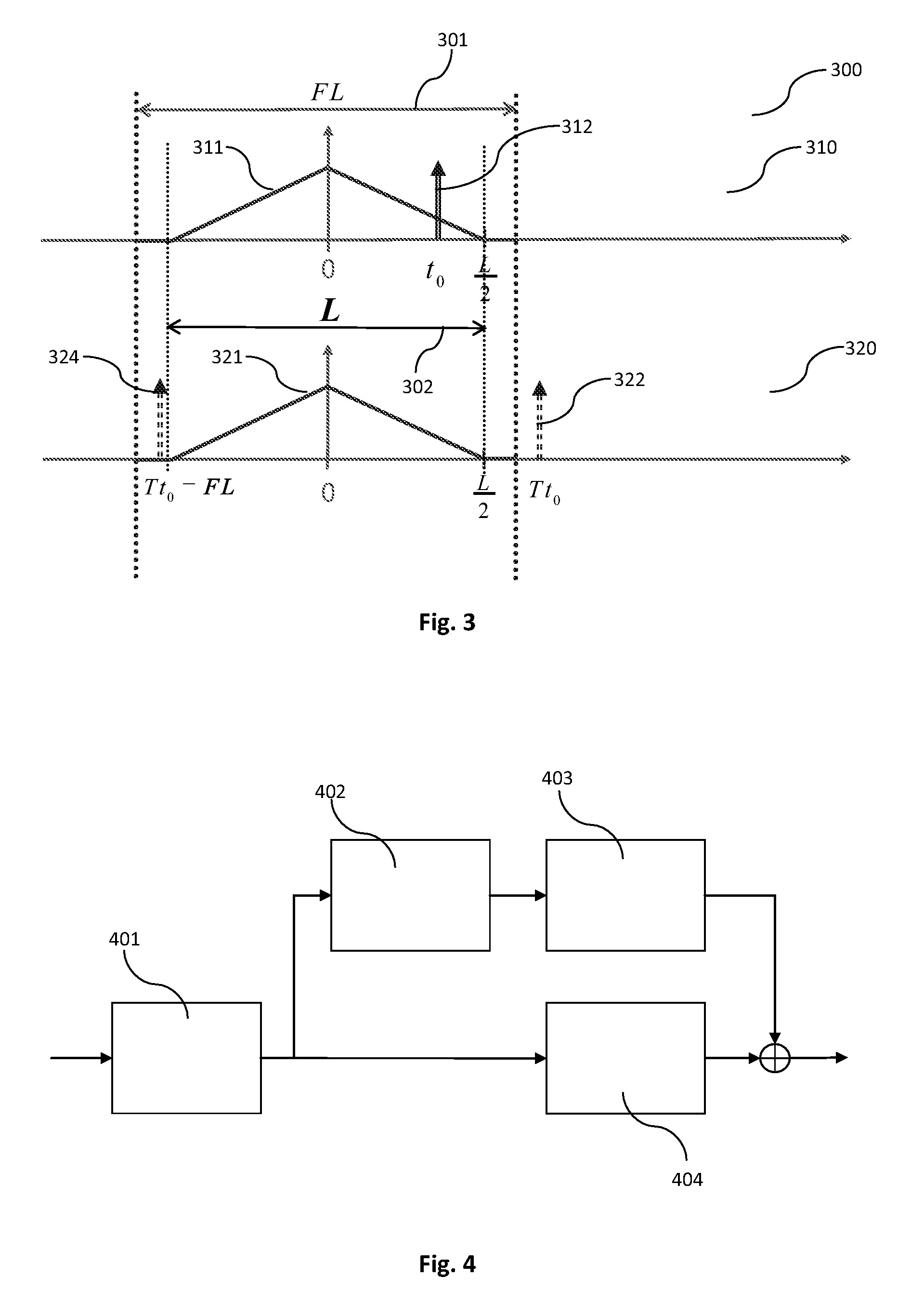
[0077]To obtain an analysis / synthesis window pair that suppresses aliasing for even transposition factors, several embodiments will be outlined in the following. the windows or prototype filters are made long enough to attenuate the level of the first side lobe in the frequency response below a certain “aliasing” level. The analysis time stride Δta will in this case only be a (small) fraction of the window length L. This typically results in smearing of transients, e.g. in percussive signals.

second embodiment

[0078] the analysis window va(n) is chosen to have dual zeros on the unit circle. The phase response resulting from a dual zero is a 360 degree phase shift. These phase shifts are retained when the phase angles are multiplied with the transposition factors, regardless if the transposition factors are odd or even. When a proper and smooth analysis filter va(n), having dual zeros on the unit circle, is obtained, the synthesis window is obtained from the equations outlined above.

[0079]In an example of the second embodiment, the analysis filter / window va(n) is the “squared sine window”, i.e. the sine window

v(n)=sin(πL(n+0.5)),0≤n<L

convolved with itself as va(n)=v(n)v(n). However, it should be noted that the resulting filter / window va(n) will be odd symmetric with length La=2L−1, i.e. an odd number of filter / window coefficients. When a filter / window with an even length is more appropriate, in particular an even symmetric filter, the filter may be obtained by first convolving two sine ...


PUM


Abstract

The present invention relates to transposing signals in time and/or frequency and in particular to coding of audio signals. More particular, the present invention relates to high frequency reconstruction (HFR) methods including a frequency domain harmonic transposer. A method and system for generating a transposed output signal from an input signal using a transposition factor T is described. The system comprises an analysis window of length La, extracting a frame of the input to signal, and an analysis transformation unit of order M transforming the samples into M complex coefficients. M is a function of the transposition factor T. The system further comprises a nonlinear processing unit altering the phase of the complex coefficients by using the transposition factor T, a synthesis transformation unit of order M transforming the altered coefficients into M altered samples, and a synthesis window of length Ls, generating a frame of the output signal.

Description

CROSS REFERENCE TO RELATED APPLICATIONS[0001]This application claims priority to U.S. Provisional Patent Application No. 61 / 243,624 filed Sep. 18, 2009 and PCT Application No. PCT / EP2010 / 053222, filed Mar. 12, 2010 hereby incorporated by reference in its entirety.TECHNICAL FIELD[0002]The present invention relates to transposing signals in frequency and / or stretching / compressing a signal in time and in particular to coding of audio signals. In other words, the present invention relates to time-scale and / or frequency-scale modification. More particularly, the present invention relates to high frequency reconstruction (HFR) methods including a frequency domain harmonic transposer.BACKGROUND OF THE INVENTION[0003]HFR technologies, such as the Spectral Band Replication (SBR) technology, allow to significantly improve the coding efficiency of traditional perceptual audio codecs. In combination with MPEG-4 Advanced Audio Coding (AAC) it forms a very efficient audio codec, which is already ...

Claims


Application Information

Patent Timeline
IPC IPC(8): G10L19/00G10L19/022G10L21/038G10L21/04
CPCG10L19/022G10L21/04G10L21/038G10L19/24G10L19/0212
Inventor EKSTRAND, PERVILLEMOES, LARS
Owner DOLBY INT AB
Learn More