
Large rc time-constant generation for audio amplifiers

a technology of time-constant generation and amplifiers, applied in pulse manipulation, pulse technique, instruments, etc., can solve problems such as transient related problems in the conventional amplifier circui

Inactive Publication Date: 2010-05-27
NUVOTON
View PDF1 Cites 3 Cited by
  • Summary
  • Abstract
  • Description
  • Claims
  • Application Information

AI Technical Summary

Benefits of technology

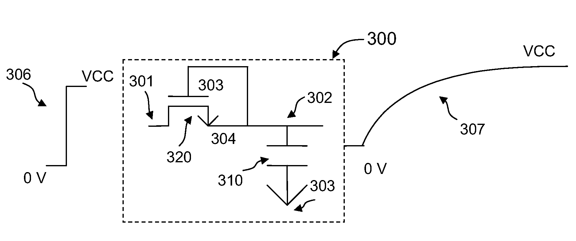
[0024]Many benefits are achieved by way of the present invention over conventional techniques. For example, the present technique provides an easy to use design that that is compatible with conventional integrated circuit design and fabrication process technologies. In certain embodiments, the invention provides techniques for generating large RC time-constants. In a specific embodiment, the circuit includes an MOS transistor configured to operate in the saturation mode and provide a large time-constant during signal transition without the penalty of having to use a large on-chip resistance. Merely as an example, an embodiment of the invention is applied to an audio system for suppressing transient noise such as pop noise in an audio amplifier. It is understood, however, the technique can be easily adopted for other applications, such as providing a long delay time between different stages of a circuit. Depending upon the embodiment, one or more of these benefits may be achieved. These and other benefits will be described in more detail throughout the present specification and more particularly below.

Problems solved by technology

As noted above, conventional amplifier circuits often suffer from transient related problems, such as pop noise during power-up or power-down.

Method used


Image

  • Large rc time-constant generation for audio amplifiers
  • Large rc time-constant generation for audio amplifiers
  • Large rc time-constant generation for audio amplifiers

Examples


Embodiment Construction

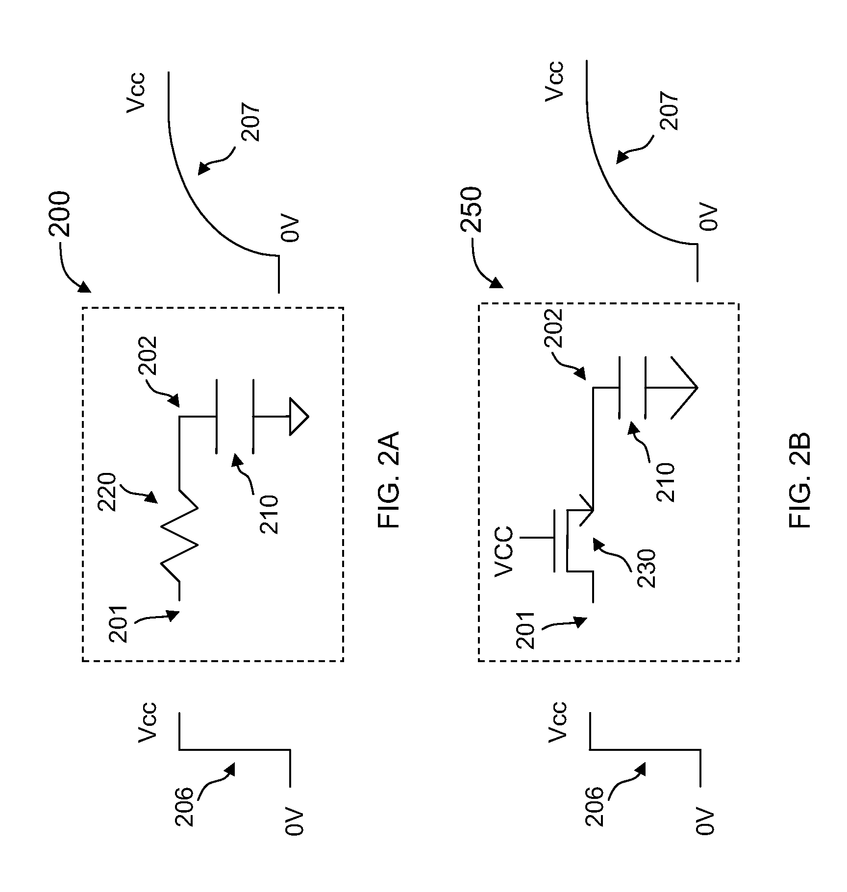
[0037]FIGS. 2A and 2B are simplified schematic diagrams illustrating two conventional low pass filters for RC time-constant generation. In FIG. 2A, resistor 220 and capacitor 210 forms an RC circuit having a time-constant related to R*C, a product of the resistance of resistor 320 and the capacitance of capacitor 210. As input signal 206 makes the transition from 0V to Vcc, for example, output signal 207 also makes a transition from 0V to a voltage close to Vcc. As shown, the output signal rises more slowly than the input signal 206, the rise time is related the time-constant RC. In FIG. 2B, the resistor is replaced by an NMOS transistor 230 with a gate voltage of Vcc. In this configuration, transistor 230 functions like a resistor, and circuit 250 operates like an RC filter. In both circuits 200 and 250, the resistance is limited by the size of the resistor or transistor. To generate a large time-constant, one way to increase the resistance both circuit is to use a resistor or tran...


PUM


Abstract

A circuit for generating a large RC time-constant includes an input node for receiving an input signal making a transition from a first state to a second state characterized by a first time-constant, and an output node for providing an output signal making a transiting from the first state to the second state in response to the input signal. The circuit also includes a first MOS field effect transistor coupled between the input node and the output node. The circuit further includes a first capacitor coupled between the output node and a ground node. A switch circuit is connected to a gate of the first MOS field effect transistor. The switch circuit is configured to bias the MOS field effect transistor to operate in saturation mode and the transition of the output signal is characterized by a time-constant associated with this large output resistance and the capacitor coupled to the output node.

Description

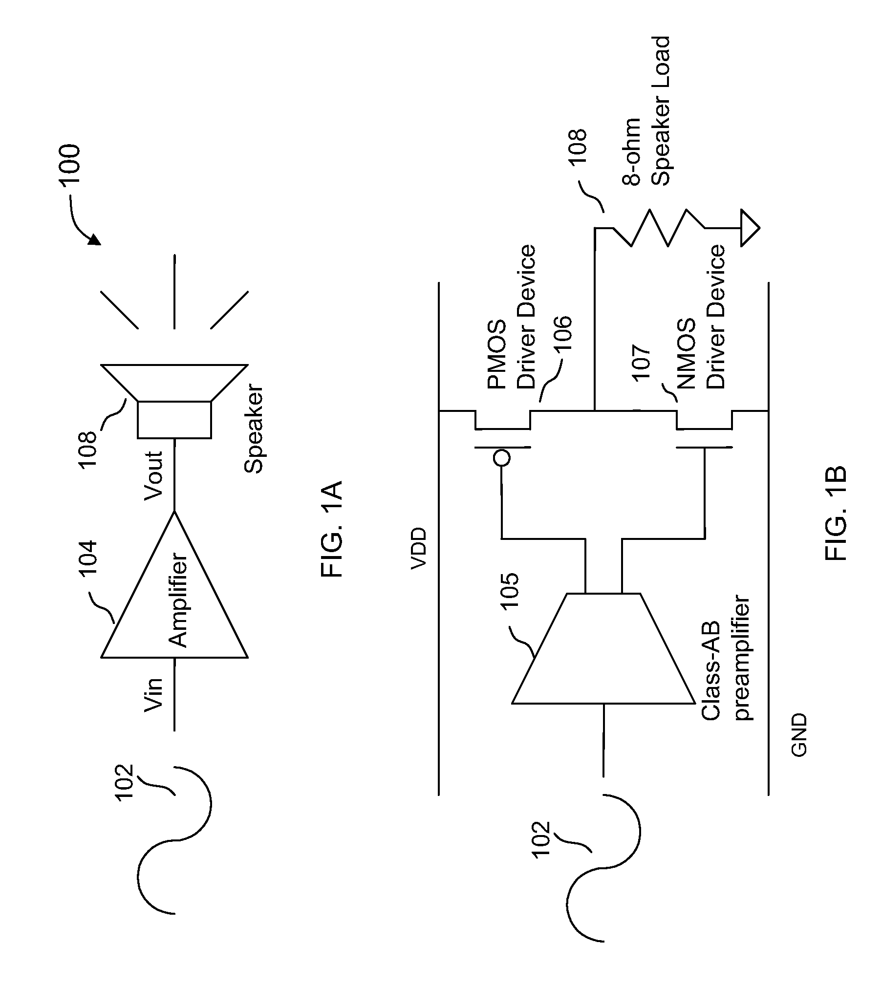
BACKGROUND OF THE INVENTION[0001]The present invention relates generally to electronic circuit techniques. More specifically, embodiments of the present invention relate to techniques for cost effective large time-constant generation. Merely by way of example, embodiments of the invention have been applied to audio amplifier and systems in applications, such as pop-noise suppression. But it would be recognized that the invention has a much broader range of applicability.[0002]Amplifier circuits are prevalent in modern electronic devices. An electronic amplifier is a device for increasing the power and / or amplitude of a signal. In particular, power amplifier circuits are used at the output stage of a system to drive an external device, such as a speaker. Power amplifier circuits output stages can be classified as A, B, AB and C for analog designs, and class D and E for switching designs. This classification is based on the portion of the input signal cycle during which the amplifying...

Claims


Application Information

Patent Timeline
IPC IPC(8): H04B15/00H03K4/04
CPCH03F1/305H03F3/181H03K2005/00156H03K5/13H03G3/348
Inventor WONG, LANCE M.
Owner NUVOTON
Learn More