
Low pass filter

a filter and low-pass technology, applied in the field of low-pass filter, can solve the problem of increasing the design cost accordingly, and achieve the effect of large time constan

Active Publication Date: 2005-03-31
REALTEK SEMICON CORP
View PDF6 Cites 0 Cited by
  • Summary
  • Abstract
  • Description
  • Claims
  • Application Information

AI Technical Summary

Benefits of technology

It is therefore one of the many objectives of the present invention to provide a low pass filter with a large time constant.

Problems solved by technology

However in an integrated circuit, a capacitor and a resistor having large values occupy too much area, so that the cost of the design increases accordingly.

Method used


Image

  • Low pass filter
  • Low pass filter
  • Low pass filter

Examples


Embodiment Construction

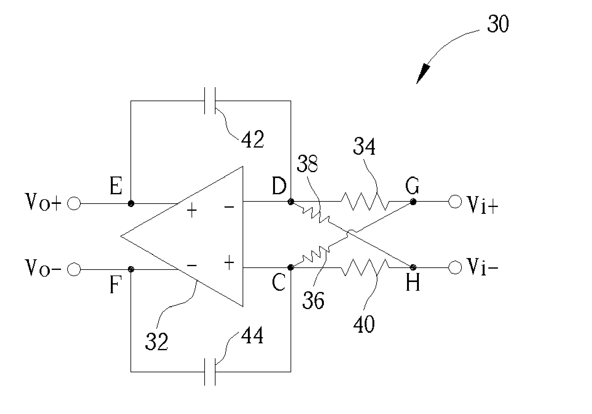
Please refer to FIG. 3 showing a low pass filter according to an embodiment of the present invention. In this embodiment, the low pass filter 30 is connected in a differential configuration, for low pass filtering a first input signal Vi+ and a second input signal Vi−, in order to generate a first output signal Vo+ and a second output signal Vo−.

The low pass filter 30 in FIG. 3 includes a differential amplifier 32 having a positive input end C, a negative input end D, a positive output end E, and a negative output end F. A first resistive device 34 is coupled between the negative input end D and a first node G, a second resistive device 36 is coupled between the positive input end C and the first node G. A third resistive device 38 being substantially the same as the second resistive device 36 is coupled between the negative input end D and a second node H, and a fourth resistive device 40 being substantially the same as the first resistive device 34 is coupled between the positi...


PUM


Abstract

A low pass filter includes a differential amplifier including a positive input end, a negative input end, a positive output end, and a negative output end. A first resistive device is coupled between the negative input end and a first node. A second resistive device is coupled between the positive input end and the first node. A third resistive device substantially the same as the second resistive device is coupled between the negative input end and a second node. A fourth resistive device substantially the same as the first resistive device is coupled between the positive input end and the second node. A first capacitive device is coupled between the negative input end and the positive output end. Finally, a second capacitive device substantially the same as the first capacitive device is coupled between the positive input end and the negative output end.

Description

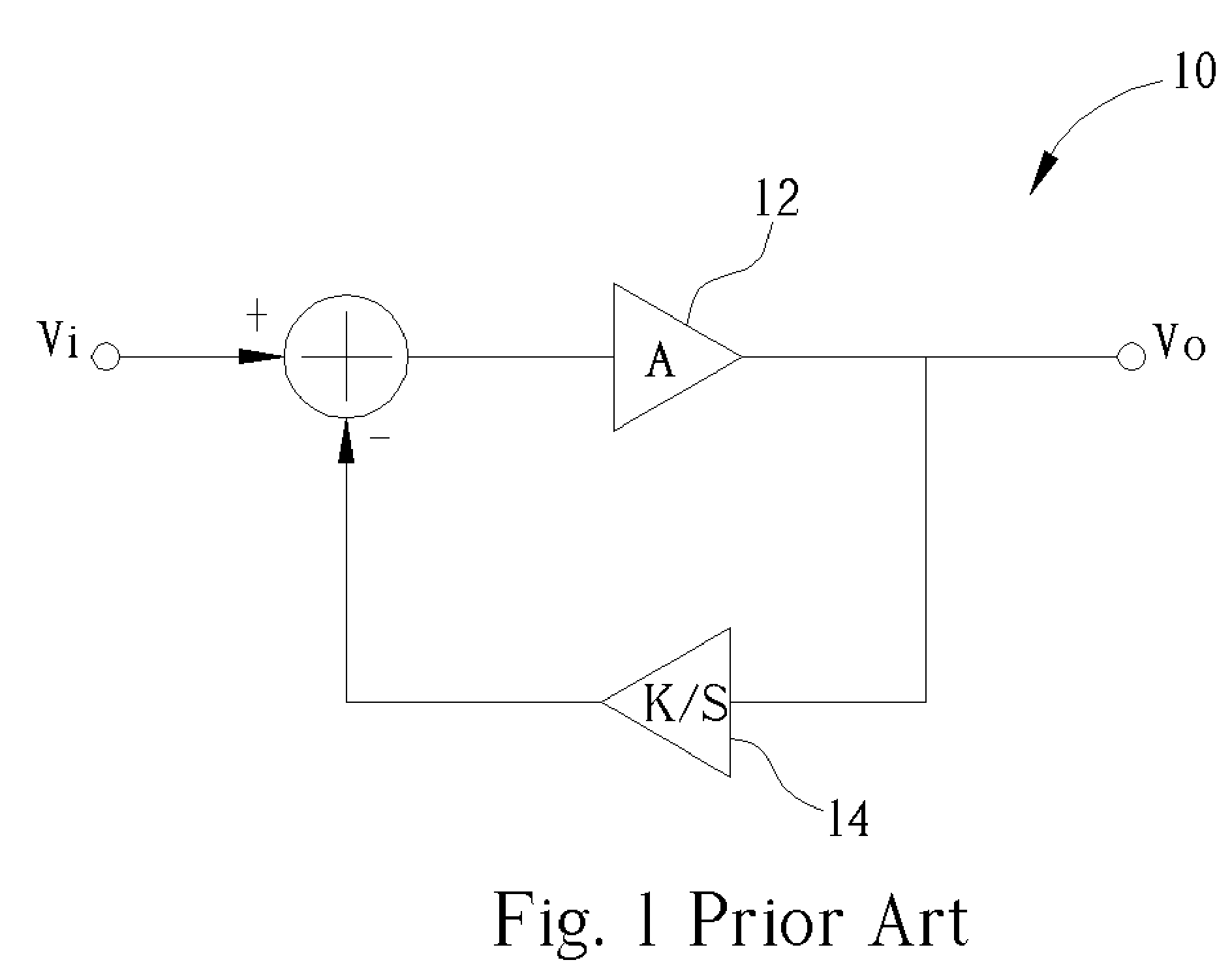
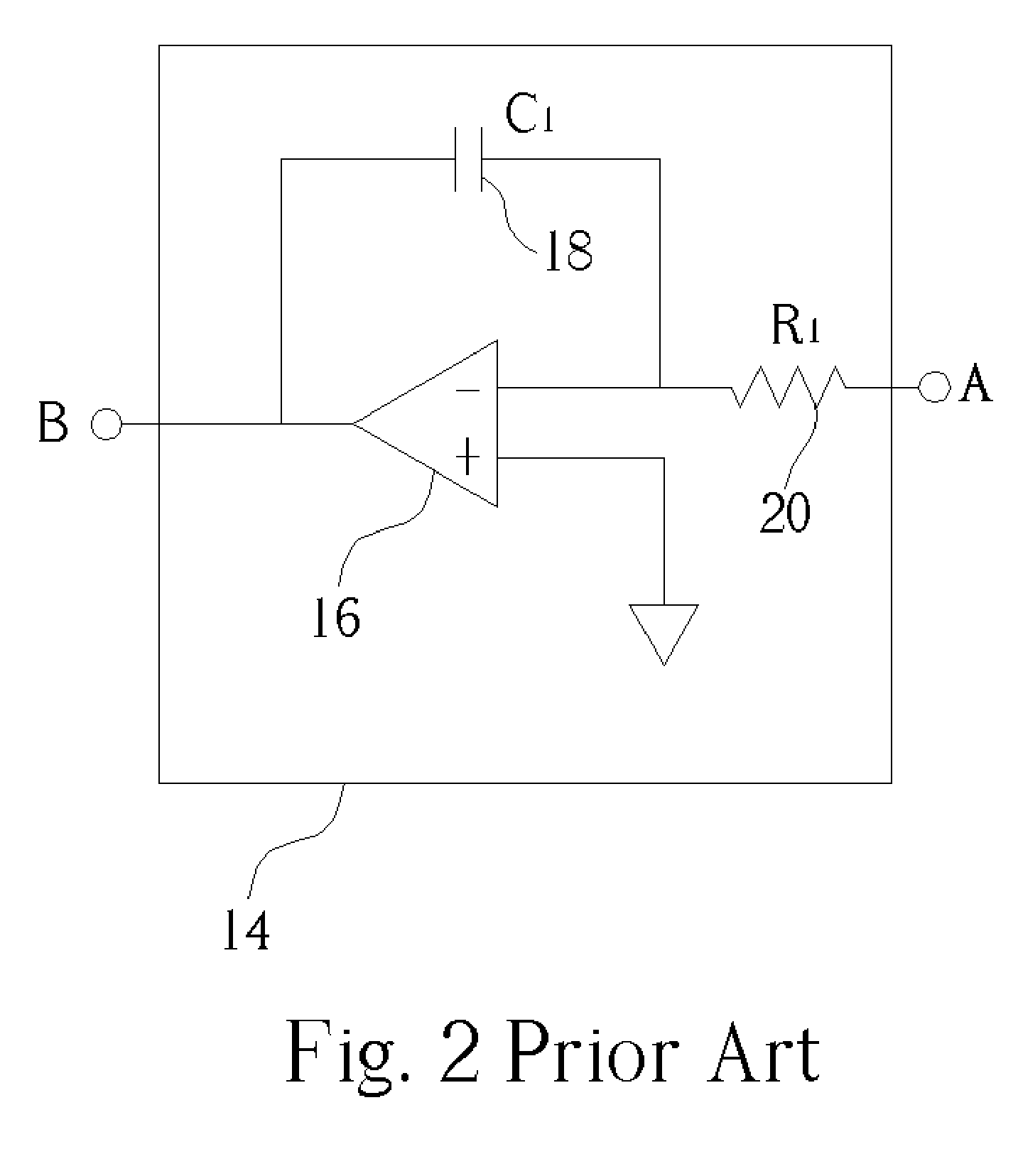
BACKGROUND OF INVENTION 1. Field of the Invention The present invention relates to a low pass filter, and more specifically, to a low pass filter with a large time constant. 2. Description of the Prior Art The low pass filter is a common device in various types of circuits including a conventional servo loop 10 shown in FIG. 1. Generally speaking, the conventional servo loop 10 is used for providing a high pass filtering characteristic between an input signal Vi and an output signal Vo. To act as a high pass filter, the servo loop 10 is composed of a gain device 12 and a low pass filter 14 connected in a negative feedback configuration. As shown in FIG. 1, k / s represents a transfer function of the low pass filter 14, which includes a pole when s=0, while k is a constant corresponding to a time constant of the low pass filter 14. Please refer to FIG. 2 showing a circuit diagram of the low pass filter 14. Node A is connected to the output voltage Vo in FIG. 1, and node B is fed b...

Claims


Application Information

Patent Timeline
Patent Type & Authority Applications(United States)
IPC IPC(8): H02H3/20H03F3/191H03H11/12H03H11/24H03K5/00
CPCH03H11/245H03H11/126
Inventor CHANG, CHIA-JUNLEE, CHAO-CHENG
Owner REALTEK SEMICON CORP
Learn More