
Adaptive delay alignment in polar transmitters

a delay alignment and polar transmitter technology, applied in the field of polar transmitters, can solve the problems of reducing the modulation accuracy of the transmitter, affecting the performance of the transmitter, and the peaks of the non-constant envelope signal to be undetectedly clipped, so as to reduce the delay mismatch

Active Publication Date: 2010-05-20
PANASONIC CORP
View PDF14 Cites 14 Cited by
  • Summary
  • Abstract
  • Description
  • Claims
  • Application Information

AI Technical Summary

Benefits of technology

[0015]Methods and apparatus for adaptively aligning delays in the amplitude modulation (AM) and phase modulation (PM) paths of a polar transmitter are disclosed. An exemplary polar transmitter includes a power amplifier (PA), an AM path including an AM path adjustable delay, an AM path delay measurement circuit, a PM path including a PM path adjustable delay, and a PM path delay measurement circuit. The AM path delay measurement circuit is configured to measure an AM path delay using waveform correlation, which in one embodiment includes sensing peak magnitude events (PMEs) in signals transmitted along the AM path to a power supply port of the PA. The PM path delay measurement circuit is configured to measure a PM path delay also using waveform correlation, which in one embodiment includes sensing PMEs in signals transmitted along the PM path to a phase-modulated input of the PA. The measured AM and PM path delays are used to adjust the AM and PM path adjustable delays, to reduce the delay mismatch between signals appearing at the power supply and phase-modulated input ports of the polar transmitter's PA.
[0016]According to one embodiment, the polar transmitter includes a digital delay comparator, and the AM and PM path delay measurement circuits each includes a clock generator and a period-to-digital converter (PDC). The clock generator and PDC of the AM path delay measurement circuit operate to generate an AM path digital word indicative of the AM path delay. Similarly, the clock generator and PDC of the PM path delay measurement circuit operate to generate a PM path digital word indicative of the PM path delay. The digital comparator operates to compare the AM path digital word to the PM path digital word and adjust the AM path adjustable delay relative to the PM path adjustable delay depending on a result of the comparison, thereby reducing the delay mismatch between the signals applied to the power supply and phase-modulated input ports of the polar transmitter's PA.
[0017]In another embodiment, the polar transmitter includes a phase-frequency detector. AM path and PM path delay clocks are generated by AM path and PM path clock generators, in response to PMEs in AM and PM signals in the AM and PM paths, respectively. The phase-frequency detector operates to reduce the phase and / or frequency difference between the AM and PM path delay clocks, and in so doing generates delay control signals for the AM path and PM path adjustable delays, to reduce the delay mismatch between the signals applied to the power supply and phase-modulated input ports of the polar transmitter's PA.

Problems solved by technology

Failure to back-off the power causes the peaks of the nonconstant-envelope signals to be undesirably clipped.
The resulting distortion reduces the modulation accuracy of the transmitter and makes it difficult to comply with communications standards and governmental regulations.
However, it also undesirably results in a significant reduction in energy efficiency.
Efficiency is therefore high when the PA is operating at a high RF output power, but low when the PA is operating at low RF output powers.
The low energy efficiency of conventional quadrature-modulator-based transmitters is a major problem, particularly in mobile handset applications since the transmitter and its PA are powered by a battery.
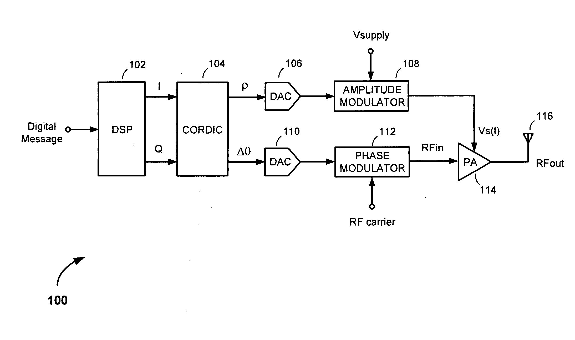
Although the polar transmitter 100 is capable of processing and transmitting nonconstant-envelope signals at high efficiencies, recomposition of the AM and PM information at the output of the PA 114 can be difficult due to the fact that the AM and PM are processed independently, i.e., in the separate AM and PM paths.
The different levels of signal processing and difference in delays presented to signals in the AM and PM paths results in a misalignment (i.e., a delay mismatch) of the signals arriving at the power supply and RF input ports of the PA 114.
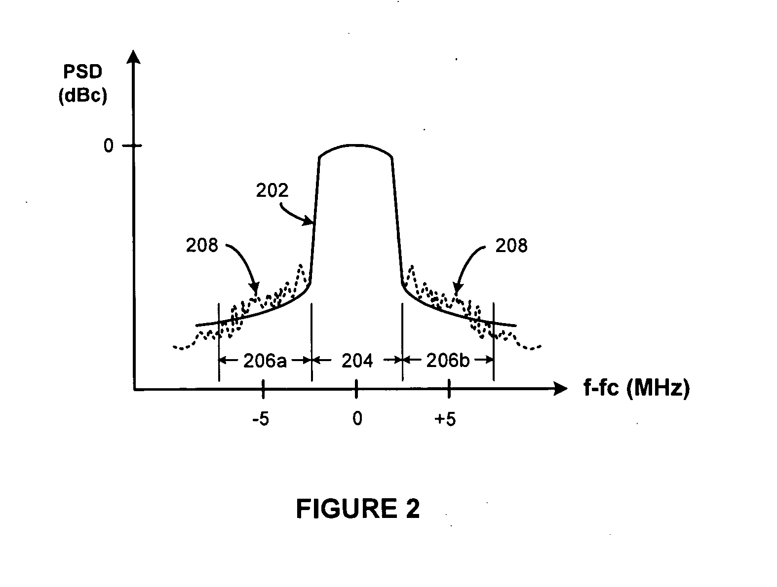
Failure to reduce the delay mismatch degrades the modulation accuracy of the polar transmitter 100 and undesirably leads to the generation of out-of-band signal energy at the output of the PA 114, making it difficult, or in some cases even impossible, to comply with communications standards.
If the delay mismatch is too high, the spectral mask requirements cannot be satisfied.
In wideband applications, however, such as W-CDMA and next-generation wideband applications, the PVT variations are strong enough that they can neither be ignored nor sufficiently compensated for in preoperational mode calibration processes.

Method used


Image

  • Adaptive delay alignment in polar transmitters
  • Adaptive delay alignment in polar transmitters
  • Adaptive delay alignment in polar transmitters

Examples


Embodiment Construction

[0031]The present invention is applicable to polar transmitter methods and apparatus configured to operate in accordance with nonconstant-envelope modulation schemes that produce nonconsant-envelope modulation signals having trajectories that pass through or close to the origin in the complex in-phase and quadrature phase (I-Q) signal plane, as illustrated in FIG. 3. For example, the invention is applicable to third generation Wideband Code Division Multiple Access (W-CDMA) cellular communication modulation schemes, orthogonal frequency-division multiple access (OFDMA) modulation schemes employed in wireless metropolitan area networks (WiMAX) and the soon to be deployed fourth generation Long Term Evolution (LTE) Universal Mobile Telecommunications System (UMTS) upgrade (i.e., High Speed OFDM Packet Access (HSOPA)), and other nonconstant-envelope modulation schemes producing signal trajectories passing through or close to the origin in the I-Q signal plane, particularly those noncon...


PUM


Abstract

A polar transmitter includes a power amplifier (PA), an amplitude modulation (AM) path including an AM path adjustable delay, an AM path delay measurement circuit, a phase modulation (PM) path including a PM path adjustable delay, and a PM path delay measurement circuit. The AM path delay measurement circuit is configured to measure an AM path delay using waveform correlation, e.g., using peak magnitude events (PMEs) in signals transmitted along the AM path to a power supply port of the PA. The PM path delay measurement circuit is configured to measure a PM path delay using waveform correlation, e.g., using PMEs in signals transmitted along the PM path to a phase-modulated input of the PA. The measured AM and PM path delays are used to adjust the AM and PM path adjustable delays, to reduce the delay mismatch between signals appearing at the power supply and phase-modulated input ports of the polar transmitter's PA.

Description

FIELD OF THE INVENTION[0001]The present invention relates to polar transmitters. More specifically, the present invention relates to methods and apparatus for adaptively aligning delays in the amplitude and phase modulation paths of a polar transmitter.BACKGROUND OF THE INVENTION[0002]To increase the amount of information that can be transmitted in a given bandwidth of the radio frequency (RF) spectrum, i.e., to increase what is referred to in the art as “spectral efficiency,” state-of-the-art and evolving wireless communications technologies, such as the Wideband Code Division Multiple Access (W-CDMA) air interface used in third generation (3G) Universal Mobile Telecommunications System (UMTS) cellular networks, and the Evolved UMTS Terrestrial Radio Access (E-UTRA) air interface proposed for use in the fourth generation (4G) Long Term Evolution (LTE) UMTS cellular network upgrade, employ nonconstant-envelope modulation schemes.[0003]Although more spectrally efficient than constant...

Claims


Application Information

Patent Timeline
IPC IPC(8): H04B1/02H04B1/04
CPCH04B1/0483
Inventor OSMAN, SALEHMCCUNE, JR., EARL W.
Owner PANASONIC CORP
Learn More