Light emiting device and method of making same

Active Publication Date: 2010-05-20
TOYODA GOSEI CO LTD
View PDF7 Cites 83 Cited by
  • Summary
  • Abstract
  • Description
  • Claims
  • Application Information

AI Technical Summary

Benefits of technology

[0034]A light emitting device according to one embodiment of the invention is constructed such that a heat dissipation member of aluminum that is difficult to bond to a solder material is provided with a bonding portion that is processed to be bonded to the solder material. Thus, the heat dissipation member can be bonded via the solder material to a light-emitting portion. Therefore, a fastening member such as a screw and a resin sheet for adhesion are not needed. As a result, the number of parts and the production steps can be decreased to reduce the production cost.

Problems solved by technology

However, the light emitting device of JP-A-2006-005290 may cause the problem that, when the housing is formed of aluminum, aluminum alloy, magnesium or magnesium alloy, oxide film will be produced on the surface of the housing such that it cannot be directly bonded to the housing via a general solder material.
Furthermore, the oxide film formed on the surface of the housing will increase a thermal resistance between the heat dissipation base and the housing to lower the heat dissipation efficiency.

Method used


Image

  • Light emiting device and method of making same
  • Light emiting device and method of making same
  • Light emiting device and method of making same

Examples


first embodiment

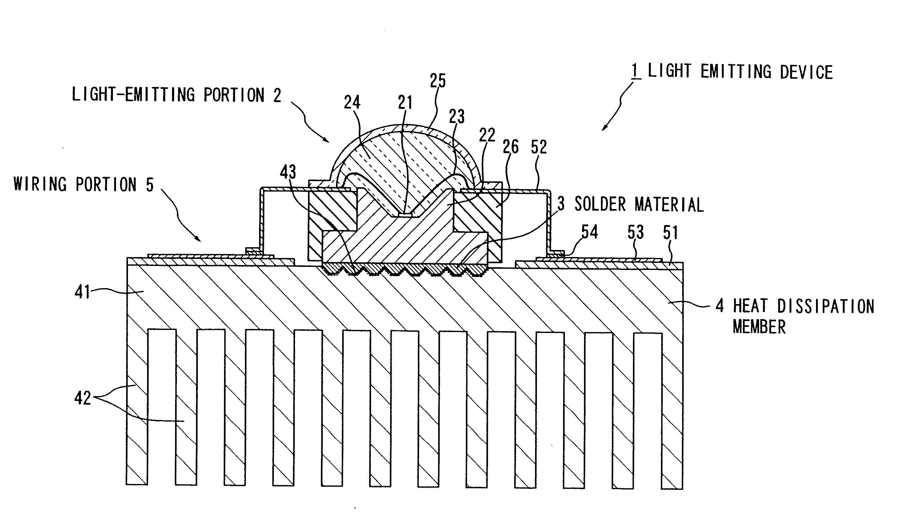
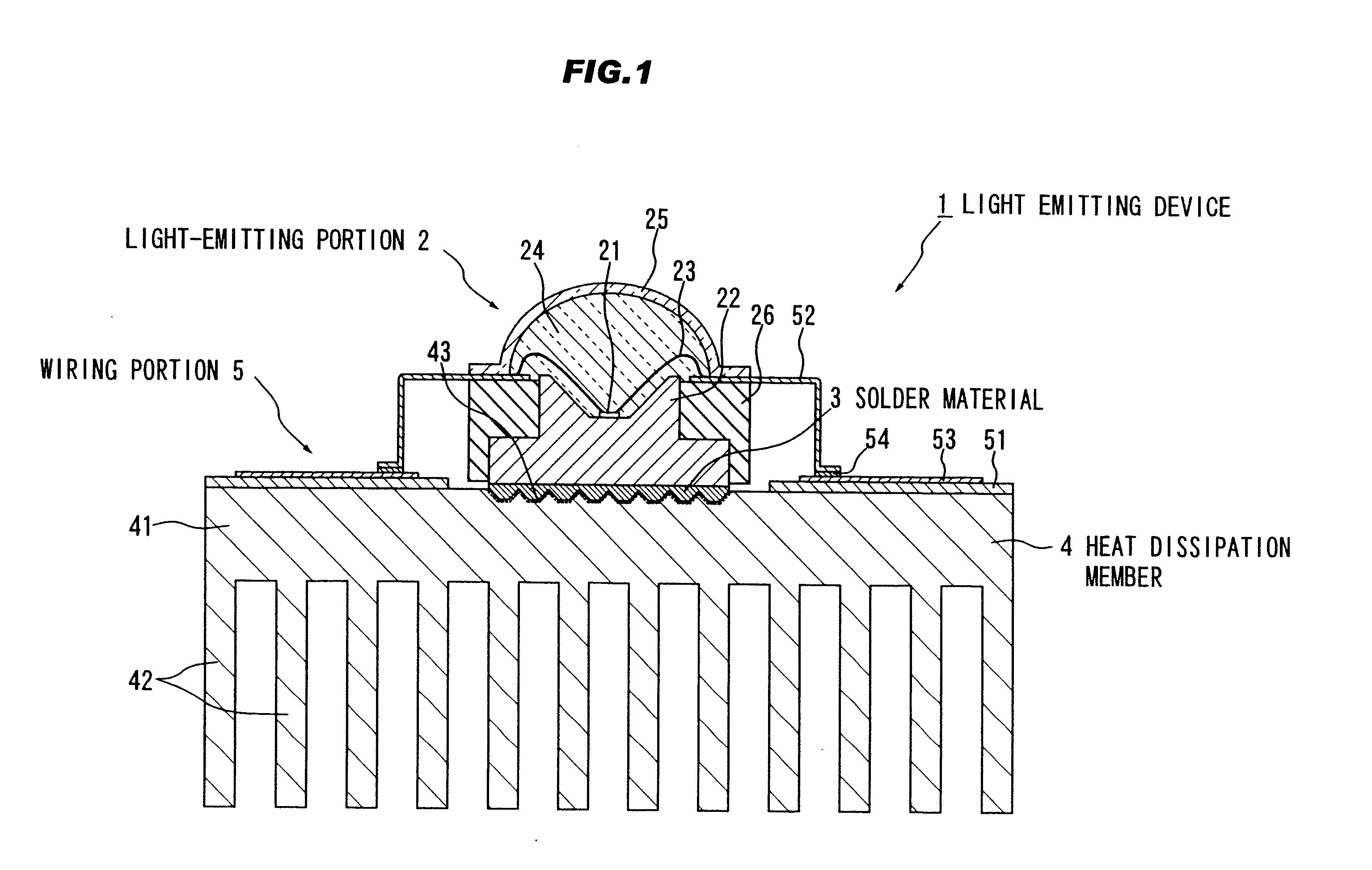
[0082]FIGS. 1 to 4 illustrate the first embodiment of the invention, where FIG. 1 is a cross sectional view showing a light emitting device in the first embodiment according to the invention.

[0083]As shown in FIG. 1, the light emitting device 1 is composed of a light-emitting portion 2 including an LED (light-emitting diode) element 21 etc., a heat dissipation member 4 connected via a solder material 3 to the light-emitting portion 2, and a wiring portion 5 for feeding power to the light-emitting portion 2. The wiring portion 5 includes a glass epoxy substrate 51 mounted on the heat dissipation member 4, and a lead 52 for connecting the glass epoxy substrate 51 and the light-emitting portion 2. The heat dissipation member 4 is of aluminum, and the solder material 3 is of a material unable to have direct adhesion to the heat dissipation member 4. Herein, “unable to have direct adhesion” means a state that it is not possible to have adhesion by metal bonding due to an oxide layer form...

second embodiment

[0107]FIG. 7 is a cross sectional view showing a light emitting device in the second preferred embodiment according to the invention.

[0108]As shown in FIG. 7, the light emitting device 101 is composed of a light-emitting portion 102 including LED (light-emitting diode) elements 121 etc., the heat dissipation member 4 connected via the solder material 3 to the light-emitting portion 102, and the wiring portion 5 for feeding power to the light-emitting portion 102. The wiring portion 5 includes the glass epoxy substrate 51 mounted on the heat dissipation member 4, and the lead 52 for connecting the glass epoxy substrate 51 and the light-emitting portion 102.

[0109]The light-emitting portion 102 is composed of the plural LED elements 121 for emitting light with a predetermined wavelength, a mount portion 122 for mounting the LED element 121 thereon, a sealing portion 124 for sealing the LED element 121 on the mount portion 122.

[0110]The LED elements 121 are each of flip-chip (or face-do...

third embodiment

[0123]FIGS. 8 to 10 show the third preferred embodiment of the invention. FIG. 8 is a perspective view showing a light emitting device in the third embodiment according to the invention.

[0124]As shown in FIG. 8, the light emitting device 201 is composed of plural light-emitting portions 202 including the LED elements 121, a heat dissipation member 204 connected via the solder material 3 to the light-emitting portions 202, and a flexible substrate 205 for feeding power to the light-emitting portions 202. The heat dissipation member 204 is formed of aluminum and formed into a plate. The light-emitting portions 202 are formed at intervals on the top surface of the heat dissipation member 204.

[0125]FIG. 9 is a cross sectional view showing the light emitting device in FIG. 8.

[0126]As shown in FIG. 9, in this embodiment, the eight light-emitting portions 202 in total are electrically in series mounted on the flexible substrate 205. The light-emitting portions 202 each include the three LE...


PUM


Abstract

A light emitting device includes a light-emitting portion including a metal part including a metal able to be bonded to a solder material, and a heat dissipation member that includes aluminum, aluminum alloy, magnesium or magnesium alloy and a bonding portion processed to be bonded to the solder material. The metal part of the light-emitting portion is bonded via the solder material to the bonding portion of the heat dissipation member. The solder material includes a material unable to be directly bonded to the heat dissipation member, the metal part of the light-emitting portion is formed by metalizing an insulation of ceramic or semiconductor, and the bonding portion includes a thermal expansion coefficient between that of the heat dissipation member and that of the insulation.

Description

[0001]The present application is based on Japanese patent application Nos. 2008-296938, 2009-082158 and 2009-219604 filed on Nov. 20, 2008, Mar. 30, 2009 and Sep. 24, 2009, respectively, the entire contents of which are incorporated herein by reference.BACKGROUND OF THE INVENTION[0002]1. Field of the Invention[0003]This invention relates to a light emitting device with a heat dissipation member formed of aluminum, aluminum alloy, magnesium or magnesium alloy. Also, this invention relates to a method of making the light emitting device.[0004]2. Description of the Related Art[0005]JP-A-2006-005290 discloses a light emitting device that is composed of a high heat conductivity heat dissipation base with a die bonding mount surface, a circuit board disposed on the heat dissipation base and having a hole for exposing a part of the mount surface and a flared portion flaring outside a peripheral edge of the heat dissipation base, a light emitting element mounted through the hole and on the ...

Claims


Application Information

Patent Timeline
IPC IPC(8): H01L33/00
CPCF21K9/00F21V29/767F21V5/043F21V29/004F21Y2101/02F21Y2103/003H01L33/642H01L2224/48091H01L2924/09701H05K1/021H05K3/341H05K2201/0347H05K2201/0373H05K2201/10106H05K2201/10969F21S48/328F21V29/763H01L2924/01019F21V29/505F21V29/75H01L2924/00014F21K9/90F21V7/005F21V29/70G02B6/0068G02B6/0085F21K9/232F21Y2103/10F21Y2115/10F21V5/10
Inventor SUEHIRO, YOSHINOBUTASUMI, KOJI
Owner TOYODA GOSEI CO LTD
Why Eureka
Try Eureka