
Systems and methods to identify interventional instruments

a technology of interventional instruments and systems, applied in the field of identifying interventional instruments, can solve the problems of affecting the visualization speed of interventional instruments, affecting the accuracy of interventional instruments, so as to facilitate rapid visualization of interventional instruments and facilitate user interaction. the effect of little or no user interaction

Inactive Publication Date: 2010-05-13
FUJIFILM SONOSITE
View PDF16 Cites 72 Cited by
  • Summary
  • Abstract
  • Description
  • Claims
  • Application Information

AI Technical Summary

Benefits of technology

[0009]The present invention is directed to systems and methods which operate to identify interventional instruments and / or other objects in images. For example, embodiments of the invention operate to extract relevant information regarding interventional instruments from a multi-dimensional volume (e.g., a 3D ultrasound field-of-view (FOV)) for presenting the information to a user in near real-time (e.g., perceived by the user as occurring in real-time) with little or no user interaction. In operation, embodiments assist image-guided interventional procedures by providing means to facilitate rapid visualization of interventional instruments and anatomical targets using volumetric data sets.
[0016]It should be appreciated that the foregoing embodiments may be utilized in addressing difficulties associated with hand-eye coordination in image-guided interventional procedures. For example, embodiments of the invention reduce the complexity of using 4D imaging by implementing semi-automatic or automatic segmentation and tracking algorithms that process 3D data sets or image volumes in near real-time to present the user with one or more 2D slices that contain the object or objects of interest (e.g., needle, catheter, surgical tool, anatomical target, etc.) as if 2D imaging is used. Although 4D imaging techniques may be employed, a user may be readily presented with an image or images (e.g., 2D and / or 3D image) having one or more objects of interest properly and appropriately therein to provide the user with desired information. This image presentation is preferably maintained in near real-time to track the identified objects throughout the procedure. Accordingly, the workflow of image-guided interventional procedures is greatly improved due to there being a high probability that an object, such as an interventional instrument, will be contained within a 3D volume rather than a thin slice associated with a 2D image plane. Although a clinician may still need to manipulate an imaging tool (e.g., ultrasound transducer) to find a target of interest (e.g. anatomical structure), once such a target has been acquired few or no additional image tool manipulations will be needed while guiding an interventional instrument to the target of interest according to embodiments of the invention. According to embodiments of the invention, the image plane and orientation of a generated image is locked to an identified interventional instrument to thereby reliably and accurately display the interventional instrument regardless of its changing positions in any dimension of the volume.
[0017]Because embodiments of the invention operate to provide an image having fewer dimensions (e.g., 2 dimensions) than a multi-dimensional (e.g., three or four dimensional) data set from which the images are generated, such multi-dimensional data sets may additionally be utilized to provide additional information to a user. For example, images in addition to an image appropriately showing an interventional instrument or other object may be provided to the user. Such additional images may be useful in enhancing the user's understanding of the anatomy with respect to the interventional instrument, to increase the user's confidence in performing the procedure, etc. As one example, in the case of ultrasound image-guided nerve blocks, physicians can have a better understanding of drug spread after the injection by simultaneously observing multiple cross-sections of the nerve, as may be generated from a 4D data set.

Problems solved by technology

However, such 2D imaging brings with it many issues associated with training and ease-of-use.
However, it is significantly more difficult for the anesthesiologist to master the hand-eye coordination required to obtain both the target anatomy (e.g., nerve) and the interventional apparatus (e.g., needle) in the same 2D image, while trying to guide the interventional apparatus towards the target.
Even more problematic, it is often difficult for the anesthesiologist to control the 2D image such that the interventional apparatus is meaningfully presented or shown in the 2D image.
Coordinating both hands for providing continuous alignment between a 3D object in space (e.g., a needle) and a relatively thin 2D slice (the image plane), while maintaining the anatomy of interest (e.g., nerve) within the image plane by observing the image displayed in the imaging device is understandably a very difficult task.
These problems are not limited to the foregoing anesthesiologist example, but are present with respect to many interventional procedures, such as biopsies, line placements, catheter placements, etc.
However, providing such freedom with respect to certain medical imaging tasks has further compounded the aforementioned hand-eye coordination problems with respect to interventional procedures.
Moreover, users in the medical field, such as the aforementioned anesthesiologists who are new to ultrasound imaging, often find it difficult if not impossible to control such images to locate and / or present the interventional apparatus and / or target in a meaningful way.
The foregoing attempts, however, require structural modification to the interventional instruments and / or imaging tools.
Such modifications are often quite complex and expensive, and in all cases limits the particular interventional instruments and / or imaging tools which are available to a user seeking to receive the benefit of such techniques.

Method used


Image

  • Systems and methods to identify interventional instruments
  • Systems and methods to identify interventional instruments
  • Systems and methods to identify interventional instruments

Examples


Embodiment Construction

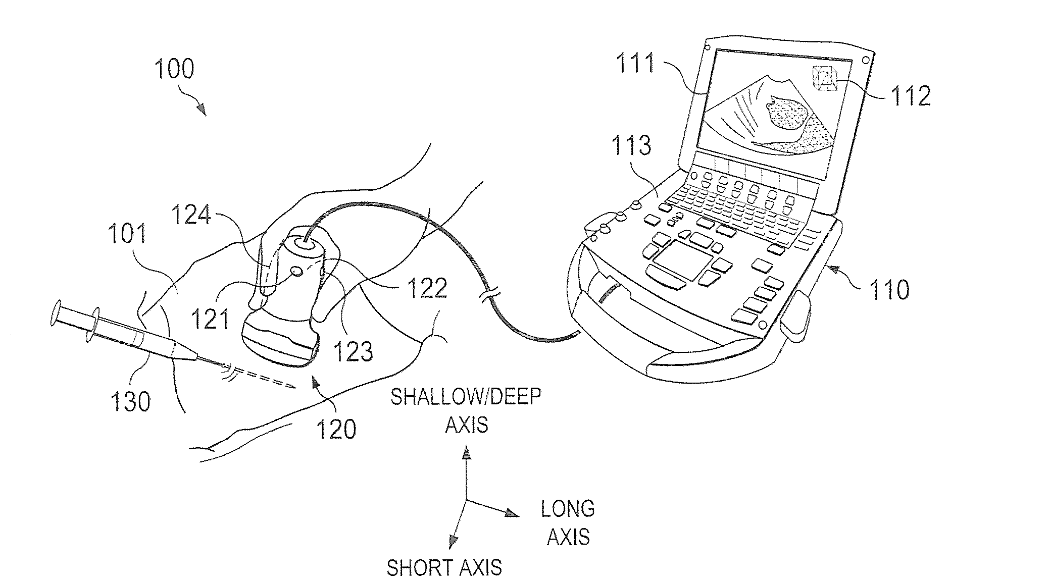
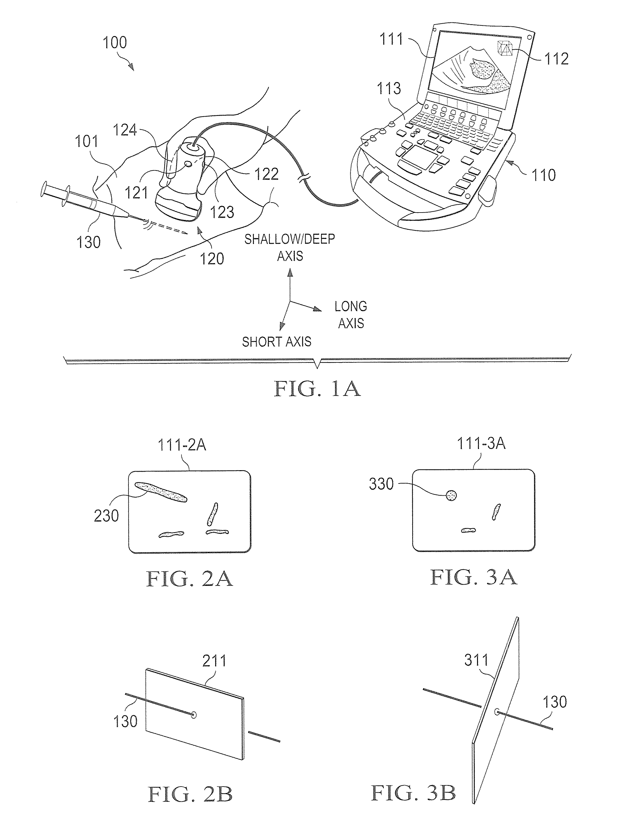
[0031]Directing attention to FIG. 1A, a system adapted according to embodiments of the invention is shown as system 100. System 100 may, for example, comprise a diagnostic ultrasound system operable to provide 2D and / or 3D images from a multi-dimensional (e.g., 3D and / or 4D) volume dataset. Although embodiments of the invention are described herein with reference to ultrasound imaging technology, in order to aid the reader in understanding the invention, it should be appreciated that the concepts of the present invention are not limited in applicability to ultrasound imaging. For example, embodiments of the present invention may be implemented with respect to fluoroscope systems, X-ray imaging systems, ultrasound imaging systems, CT imaging systems, MRI systems, positron emission tomography (PET) imaging systems, and the like.

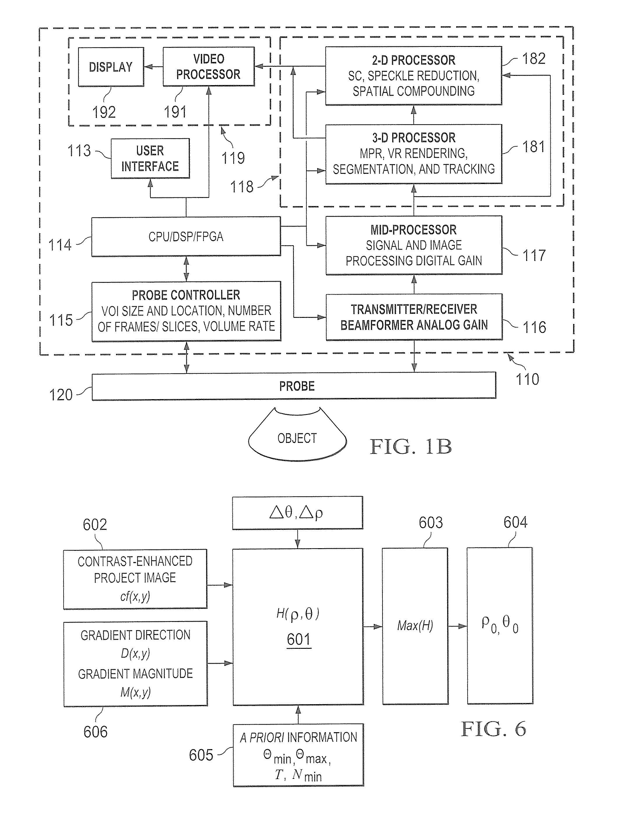
[0032]System 100 of the illustrated embodiment includes system unit 110 and transducer 120 coupled thereto. System unit 110 preferably comprises a processor-ba...


PUM


Abstract

Systems and methods which operate to identify interventional instruments and / or other objects in images are shown. Embodiments operate to extract relevant information regarding interventional instruments from a multi-dimensional volume for presenting the information to a user in near real-time with little or no user interaction. Objects may be identified by segmenting a multi-dimensional volume, identifying a putative object of interest in multiple multi-dimensional volume segments, and determining a position of the object of interest within the multi-dimensional volume using the putative object of interest segment identifications. Identification of objects of interest according to embodiments may be utilized to determine an image plane for use in displaying the objects within a generated image, to track the objects within the multi-dimensional volume, etc., such as for medical examination, interventional procedures, diagnosis treatment, and / or the like.

Description

REFERENCE TO RELATED APPLICATIONS[0001]The present application is related to co-pending and commonly assigned U.S. patent application Ser. No. [Attorney Docket No. 65744-P043US-10805627] entitled “Systems and Methods for Image Presentation for Medical Examination and Interventional Procedures”, filed concurrently herewith, the disclosure of which is hereby incorporated herein by reference.TECHNICAL FIELD[0002]The invention relates generally to identifying interventional instruments and, more particularly, to segmenting and / or tracking interventional instruments in a multi-dimensional volume, such as for medical examination, interventional procedures, diagnosis, treatment, etc.BACKGROUND OF THE INVENTION[0003]Various forms of imaging apparatus have been used extensively for medical applications. For example, fluoroscope systems, X-ray imaging systems, ultrasound imaging systems, computed tomography (CT) imaging systems, and magnetic resonance (MR) imaging (MRI) systems have been used...

Claims


Application Information

Patent Timeline
IPC IPC(8): A61B8/00G06K9/00
CPCA61B8/00A61B8/461A61B8/483G06T7/2033A61B2019/5276A61B5/061A61B8/0841A61B19/5244G06T2207/30021A61B8/463A61B8/466A61B34/20A61B2090/378G06T7/246
Inventor PAGOULATOS, NIKOLAOSMA, QINGLIN
Owner FUJIFILM SONOSITE
Learn More