Scanning optical apparatus and image forming apparatus using the same

an optical apparatus and scanning technology, applied in the direction of electrographic process apparatus, optics, instruments, etc., can solve the problems of inattention to the optical element of the incident optical system in the conventional scanning, finally correction for the fluctuation in optical performance, so as to reduce the change of an irradiation position, stable image, and high image quality

Inactive Publication Date: 2010-05-13
CANON KK
View PDF1 Cites 14 Cited by
  • Summary
  • Abstract
  • Description
  • Claims
  • Application Information

AI Technical Summary

Benefits of technology

[0023]It is an object of the present invention to provide a scanning optical apparatus and an image forming apparatus using the same, which are capable of reducing a change of an irradiation position of a light flux on a deflection unit, that is, a change of an incident position of the light flux on a surface to be scanned due to an error that may occur in a manufacturing process or in an attachment step, and of obtaining a stable image with high image quality.
[0035]According to the present invention, it is possible to provide the scanning optical apparatus and the image forming apparatus using the same, which are capable of reducing a change of the irradiation position of the light flux on the deflection unit, that is, a change of the incident position of the light flux on the surface to be scanned due to an error that may occur in the manufacturing process or in the attachment step, and of obtaining a stable image with high image quality.

Problems solved by technology

However, a manufacturing error of a component, a mounting positional error in the assembling process, and other various errors may occur when the main body is assembled, which may cause fluctuation in performance of the products.
As a typical problem caused by the fluctuation, there is a problem of a shift of an imaging position due to a tilt of imaging field generated in a deflection surface of an optical deflector.
In addition, some correction is performed finally for the fluctuation in optical performance due to the above-mentioned error.
However, such attention has not been given to the optical element of the incident optical system in the conventional scanning optical apparatus.

Method used


Image

  • Scanning optical apparatus and image forming apparatus using the same
  • Scanning optical apparatus and image forming apparatus using the same
  • Scanning optical apparatus and image forming apparatus using the same

Examples


first embodiment

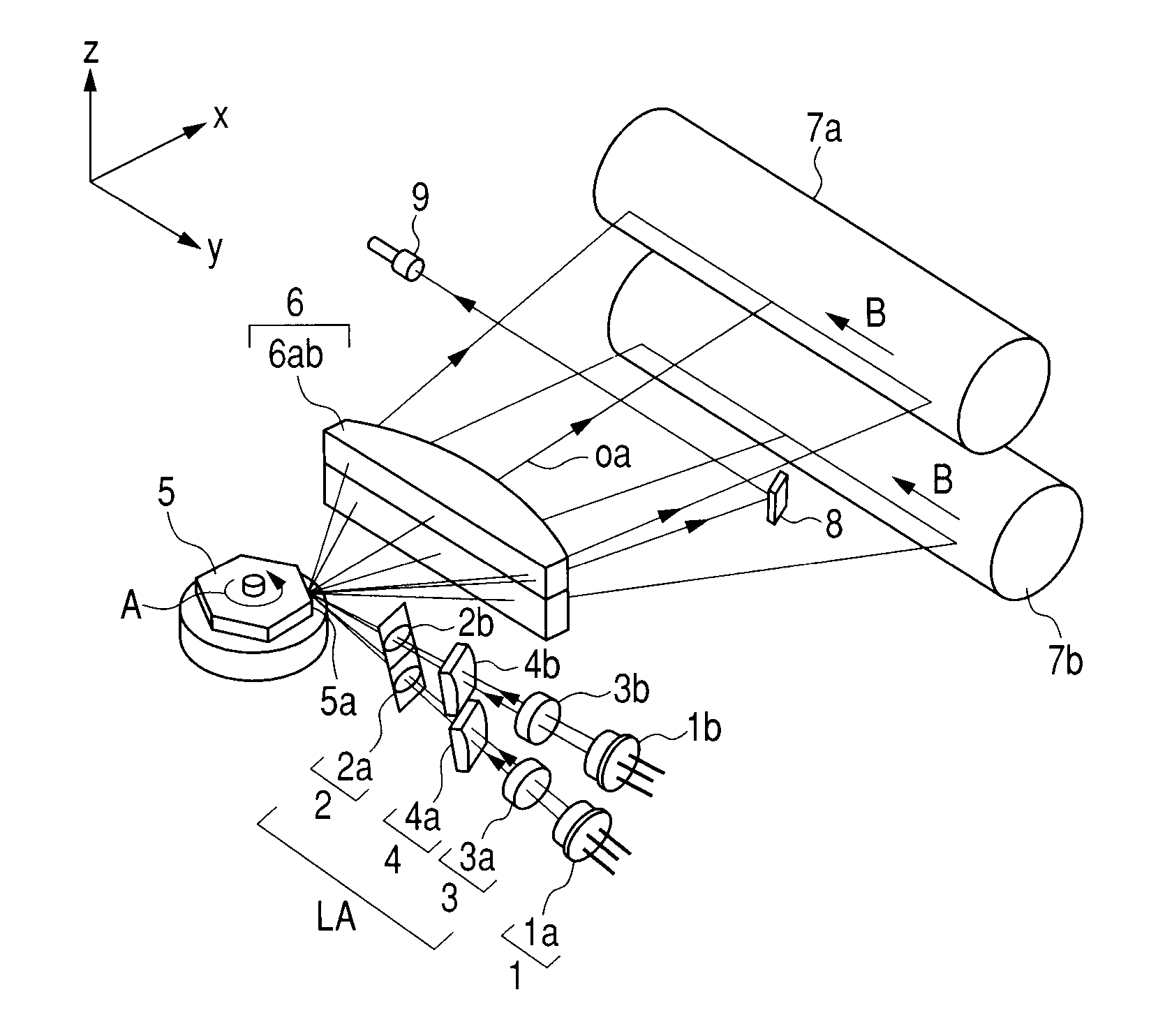
[0056]FIG. 1 is a schematic view of a main part of a scanning optical apparatus according to a first embodiment of the present invention.

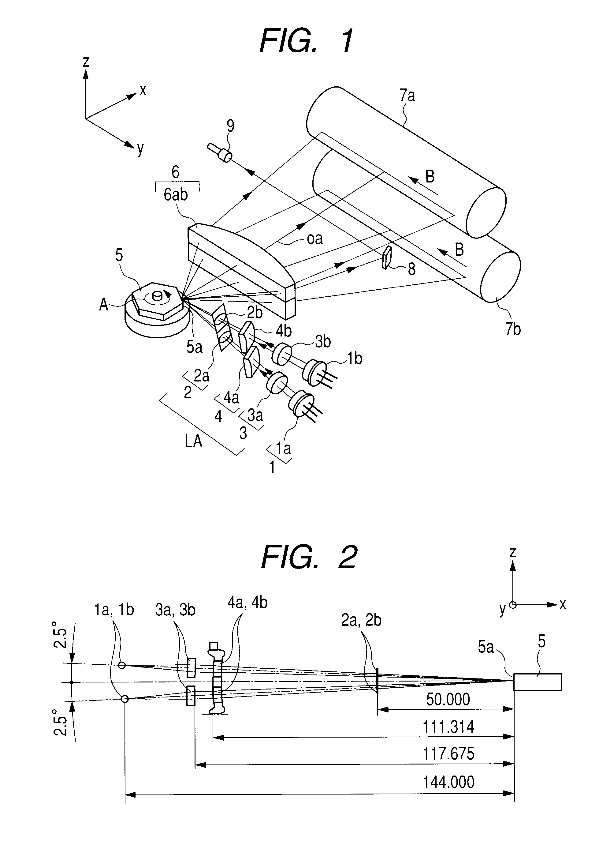
[0057]FIG. 2 illustrates a cross section (sub scanning section) of a main part in the sub scanning direction from a light source unit to a deflection unit according to the first embodiment of the present invention.

[0058]In the diagram, a light source unit 1 includes a plurality of light sources.

[0059]This embodiment illustrates the case where two light sources 1a and 1b are disposed.

[0060]Each of the light sources 1a and 1b is formed of a semiconductor laser.

[0061]Note that this embodiment uses the plurality of light sources as the light source unit, but this structure should not be interpreted as a limitation. It is also possible to use a single light source including a plurality of light emission portions for forming the light source unit.

[0062]A condensing optical system 3 includes two condensing lenses (collimator lenses) 3a and 3b.

[0063]The t...

second embodiment

[0157]FIG. 5 is a schematic diagram of a main part of a sub scanning section illustrating a structure for positioning an incident optical system in a casing according to a second embodiment of the present invention.

[0158]In FIG. 5, the same element as illustrated in FIG. 3 is denoted by the same reference symbol.

[0159]This embodiment is different from the first embodiment described above in that a positional relationship between the incident optical system 4 and a positional regulation member 23 is changed in the structure.

[0160]Other structure and the optical action are the same as those in the above-mentioned first embodiment, and hence the same effect can be obtained.

[0161]In other words, in this embodiment, the positional regulation member 23 of a casing 14 is disposed at the rear (deflection unit 5 side) of the incident optical system 4.

[0162]Thus, this embodiment is effective in the case where the incident optical system 4 is to be disposed in the light source unit 1 side.

[016...

third embodiment

[0168]FIG. 7 is a schematic diagram of a main part of a sub scanning section illustrating a structure for positioning an incident optical system in a casing according to a third embodiment of the present invention.

[0169]In FIG. 7, the same element as illustrated in FIG. 3 is denoted by the same reference symbol.

[0170]This embodiment is different from the first embodiment described above in that the light source unit is formed by a single light source.

[0171]Other structure and the optical action are the same as those in the above-mentioned first embodiment, and hence a change of the irradiation position of the light flux on the deflection unit due to an error that may occur in the manufacturing process or in the attachment is reduced.

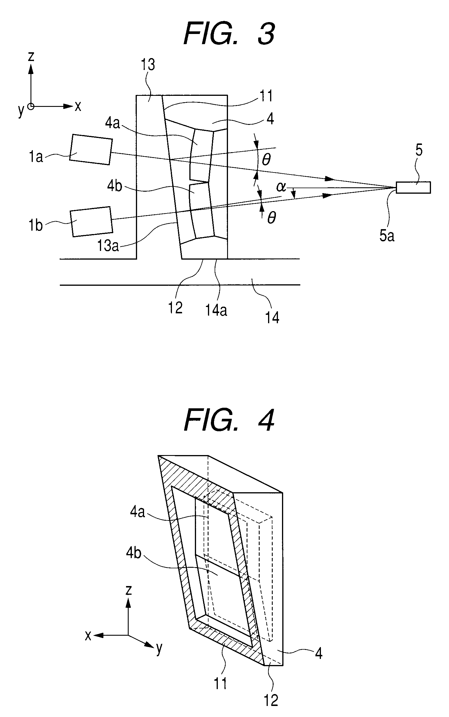
[0172]In this embodiment, the angle α between the principal ray of the light flux “a” emitted from the light source 1a and the normal of the optical deflector 5 in the sub scanning section is set to be 2.5 degrees.

[0173]Therefore, the angle θ between the...


PUM


Abstract

A scanning optical apparatus includes: an incident optical system which is disposed in an optical path between a light source unit and a deflection unit, and includes an optical element for making a light flux emitted from the light source unit enter a deflection surface of the deflection unit with an oblique angle in a sub scanning section; and a positional regulation member for holding the optical element having an x reference surface for performing positional regulation of the optical element in an optical axis direction and a z reference surface for performing positional regulation of the optical element in a sub scanning direction. The optical element is held by a casing so that the x reference surface and the z reference surface contact with the positional regulation member of the casing. The principal ray of the light flux outgoing from the optical element satisfies a conditional equation (1).

Description

BACKGROUND OF THE INVENTION[0001]1. Field of the Invention[0002]The present invention relates to an optical scanning apparatus and an image forming apparatus using the same. In particular, the present invention is suited to an image forming apparatus such as a laser beam printer, a digital copying machine, or a multifunction printer, which employs an electrophotographic process.[0003]2. Description of the Related Art[0004]In a laser beam printer, a digital copying machine, a multifunction printer, or other image forming apparatus (image output portion) employing an electrophotographic process, scanning is performed on a photosensitive member (photosensitive drum) with a light flux (laser light flux) that blinks in accordance with print data.[0005]Thus, exposure distribution is formed, and image formation is realized by an electrostatic copying mechanism in accordance with the exposure distribution.[0006]In recent years, a resin material is frequently used for imaging optical element...

Claims


Application Information

Patent Timeline
IPC IPC(8): G03G15/22G02B26/10
CPCG02B26/123G02B26/124G03G15/0435G03G2215/0404G03G15/0409
Inventor TERAMURA, MASAYASU
Owner CANON KK
Why Eureka
Try Eureka