Manufacturing method of absorbent article

a manufacturing method and absorbent article technology, applied in the field of manufacturing methods of absorbent articles, can solve the problems of reducing the durability of absorbent articles, leaking excrement from wearers, and less likely to fit the waist portion of wearers

Active Publication Date: 2010-05-13
UNI CHARM CORP
View PDF3 Cites 23 Cited by
  • Summary
  • Abstract
  • Description
  • Claims
  • Application Information

AI Technical Summary

Benefits of technology

[0016]According to the present invention, it is possible to provide a manufacturing method of an absorbent article capable of making a waist portion and a leg portion of the absorbent article less likely to be separated while keeping basic properties, such as the durability and the leakage prevention capability of the absorbent article, and additional properties, such as the disassembling property thereof, when a predetermined region corresponding to a bonded part of the absorbent article is bonded by using an ultrasonic bonding device.

Problems solved by technology

However, the aforementioned conventional technique has the following problems.
Therefore, when a wearer puts on and off an absorbent article (at the time of putting on and off), the waist portion and the leg portions can be separated easily, which consequently reduces the durability of the absorbent article.
Further, if the waist portion can be separated easily, the absorbent article is less likely to fit the waist portion of the wearer while the wearer wears the absorbent article (while being worn).
Accordingly, excrement from the wearer may leak from the absorbent article (a so-called leakage prevention capability may be deteriorated).
However, if the bonding strength of the whole predetermined region is increased, it becomes difficult to tear the bonded part (a so-called disassembling property is deteriorated) when the wearer disposes the absorbent article (at the time of disposal).

Method used


Image

  • Manufacturing method of absorbent article
  • Manufacturing method of absorbent article
  • Manufacturing method of absorbent article

Examples


first modification

(6-1) First Modification

[0079]First, a configuration of an ultrasonic bonding device 101A according to a first modification will be described with reference to the drawings. FIG. 9 is a view showing the ultrasonic bonding device 101A according to the first modification.

[0080]As shown in FIG. 9, the ultrasonic bonding device 101A is provided with two ultrasonic horns 330. In other words, the two ultrasonic horns 330 are independently provided. Ultrasonic vibrators 310 (not shown in FIG. 9, see FIG. 3) described in the embodiment are respectively provided to the two independent ultrasonic horns 330.

[0081]The two ultrasonic horns 330 are arranged so as to be aligned in the cross direction CD. An attaching position of each of the two ultrasonic horns 330 can be adjusted individually. In other words, it is possible to adjust clearances, variations, a relative position or the like of the two ultrasonic horns 330 with projecting parts 220 of an anvil roll 200. For example, the two ultrason...

second modification

(6-2) Second Modification

[0089]First, a configuration of an ultrasonic bonding device 101B according to a second modification will be described with reference to the drawings. FIG. 10 is a view showing the ultrasonic bonding device 101B according to the second modification.

[0090]As shown in FIG. 10, the ultrasonic bonding device 101B is provided with three ultrasonic horns 330. In other words, the three ultrasonic horns 330 are independently provided. Ultrasonic vibrators 310 (not shown in FIG. 10, see FIG. 3) described in the embodiment are respectively provided to the three independent ultrasonic horns 330. The three ultrasonic horns 330 are arranged so as to be aligned in the cross direction CD. An attaching position of each of the three ultrasonic horns 330 can be adjusted individually. In other words, it is possible to adjust clearances, variations, a relative position or the like of the three ultrasonic horns 330 with projecting parts 220 of an anvil roll 200. For example, thr...


PUM

PropertyMeasurementUnit
bonding strengthaaaaaaaaaa
ultrasonicaaaaaaaaaa
ultrasonic vibrationaaaaaaaaaa

Abstract

In the present invention, ultrasonic vibration is outputted to predetermined regions of a first web and a second web from an output surface of an ultrasonic horn so that the predetermined regions may be bonded. The output surface includes a central output portion in a center region of three equal regions into which each predetermined region is divided, and both-ends output portions in both-ends regions at sides of the center region. A central maximum amplitude of the ultrasonic vibration outputted from the central output portion is smaller than an end maximum amplitude of the ultrasonic vibration outputted from each of the both-ends output portions. A central bonding strength of the center region is smaller than an end bonding strength of each of the both-ends regions.

Description

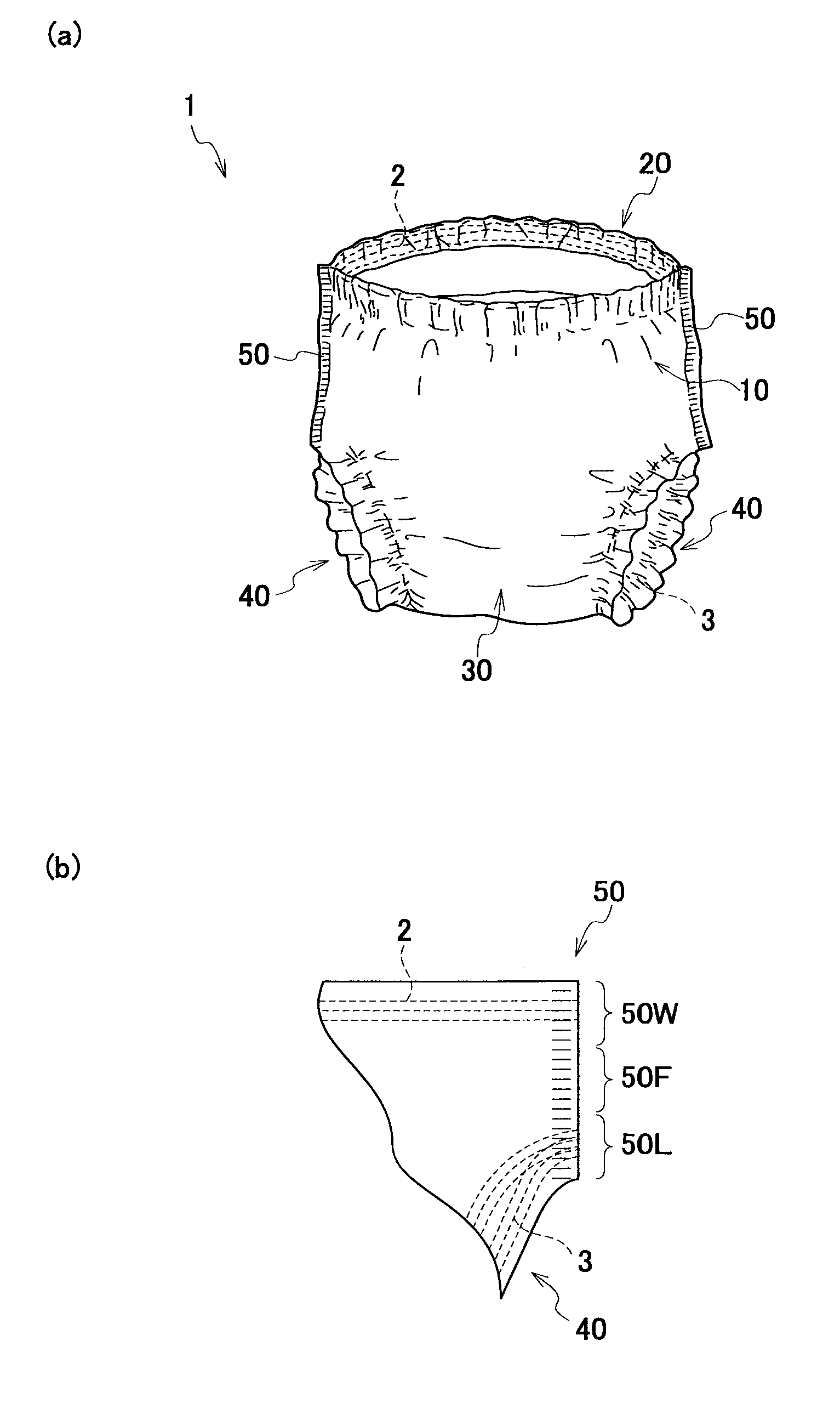
BACKGROUND OF THE INVENTION[0001]1. Field of the Invention[0002]The present invention relates to a manufacturing method of an absorbent article including a first web which constitutes a front waistband part, and a second web which constitutes a rear waistband part.[0003]2. Description of the Related Art[0004]Generally, an absorbent article, such as a disposable diaper, includes: a front waistband part which corresponds to a front portion around the waistline of a wearer; a rear waistband part which corresponds to a rear portion around the waistline of the wearer; a crotch part which corresponds to the crotch of the wearer; and leg openings which open at sides of the crotch part.[0005]The front waistband part and the rear waistband part are bonded to each other from an upper edge portion of the absorbent article from which a waistline portion of the wearer is to be inserted (i.e., an edge portion corresponding to a waist portion of the wearer) to each leg opening. These portions wher...

Claims


Application Information

Patent Timeline
Patent Type & Authority Applications(United States)
IPC IPC(8): B32B37/02
CPCA61F13/15699B29C66/1122B29C65/086B29C66/232B29C66/81467B29C66/81469B29C66/83411B29C66/83511B29C2793/009B29L2031/4878B29C66/21B29C66/431Y10T156/1084B29C66/81427A61F13/15772B29C66/83415B29C65/08A61F13/49B32B37/00
Inventor YAMAMOTO, HIROKI
Owner UNI CHARM CORP
Why Eureka
Try Eureka