
Gas Turbine Combustor, and Gas Turbine

a technology of gas turbines and combustor tubes, which is applied in the direction of machines/engines, mechanical equipment, light and heating equipment, etc., can solve the problems of deteriorating the overall efficiency of a gas turbine, increasing nox emission amounts, etc., and achieves the effect of suppressing air flow separation

Active Publication Date: 2020-07-30
MITSUBISHI HEAVY IND LTD
View PDF0 Cites 2 Cited by
  • Summary
  • Abstract
  • Description
  • Claims
  • Application Information

AI Technical Summary

Benefits of technology

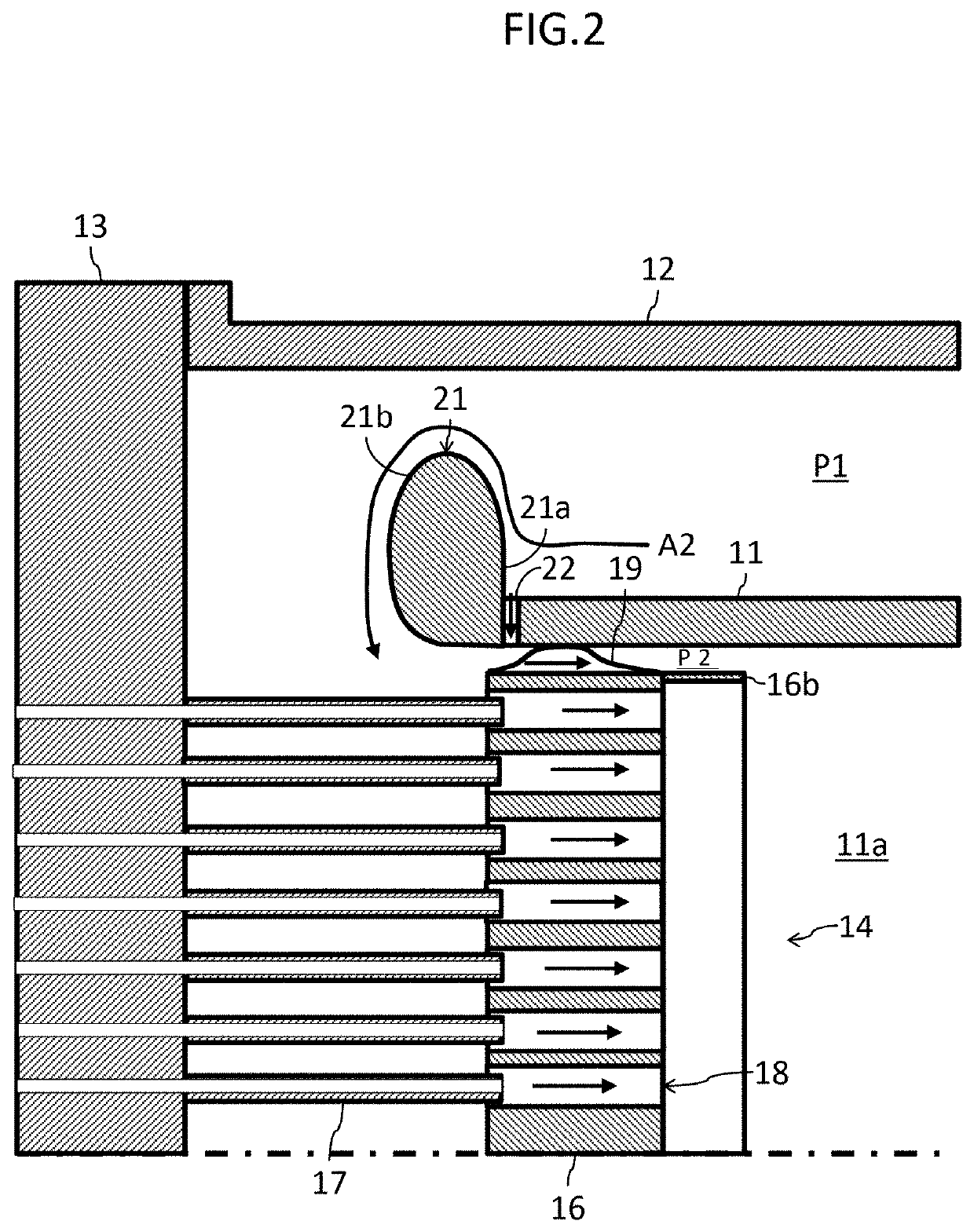
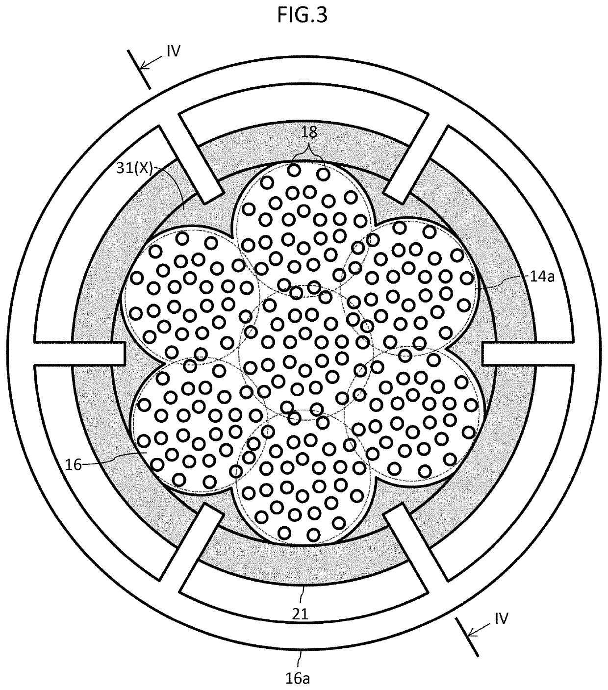
The present invention provides a gas turbine combustor and gas turbine that can suppress separation of air flows in air holes. This is achieved by designing a turn guide in a ring-like form that results in different radial positions of air holes in relation to the air hole plate depending on the layout of air holes. The distance between the turn guide and air holes is different, which affects the velocity vectors of compressed air flowing into the air holes. Combustor components in both the axial and radial directions are involved in the air flow, which helps to achieve better mixing of air and reduces separation of flows near the inlets of the air holes.

Problems solved by technology

If deviations occur in the air flow rates, deviations occur also between fuel-air ratios in air holes, flame temperature rises locally in areas where the fuel concentration is high, and this becomes a cause of increase in NOx emission amounts.
In addition, pressure loss that occurs when an air flow passes through air holes increases in areas where air flow rates are high, and this can lead also to deterioration of the overall efficiency of a gas turbine.
Accordingly, it is an important problem in uniform distribution combustion to improve uniformity among the rates of air flows through air holes.

Method used


Image

  • Gas Turbine Combustor, and Gas Turbine
  • Gas Turbine Combustor, and Gas Turbine
  • Gas Turbine Combustor, and Gas Turbine

Examples


first embodiment

Gas Turbine Plant

[0022]FIG. 1A is a schematic diagram of one example of a gas turbine plant to which a gas turbine combustor according to a first embodiment of the present invention is applied. The gas turbine plant illustrated in the figure includes a compressor 1, a gas turbine combustor, hereinafter, abbreviated to a combustor, 2, a turbine 3, and a load device 4. The compressor 1, the combustor 2, and the turbine 3 constitute a gas turbine to drive the load device 4. Although the load device 4 in the present embodiment is a power generator, a pump may be applied thereto. Note that, typically, a gas turbine is referred to as a “gas turbine engine” in some cases, and in those cases a turbine is referred to as a “gas turbine” in some cases.

[0023]The compressor 1 is rotation-driven by the turbine 3, compresses air A1 taken in from the inlet to produce high pressure compressed air, or combustion air, A2 which is to be supplied to the combustor 2. The combustor 2 mixes the compressed ...

second embodiment

[0050]FIG. 6 is a partial cross-sectional view representing the structure of main parts of a gas turbine combustor according to a second embodiment of the present invention, FIG. 7 is a configuration diagram of an air hole plate and a turn guide in the present embodiment seen from the side where the end cover is located, and FIG. 8 is a cross-sectional view taken along the line VIII-VIII in FIG. 7. FIG. 6, FIG. 7, and FIG. 8 correspond to FIG. 2, FIG. 3, and FIG. 4 illustrating the first embodiment, respectively. Elements in the present embodiment that are the same as or correspond to those in the embodiment explained already are given the same signs in FIG. 6 to FIG. 8 as those in the drawings already mentioned, and explanations thereof are omitted as appropriate.

[0051]The present embodiment is different from the first embodiment in that the auxiliary guides 31 are provided to the air hole plate 16 integrally with the turn guide 21 in the present embodiment. That is, in the present...

third embodiment

[0053]FIG. 9 is a partial cross-sectional view representing the structure of main parts of a gas turbine combustor according to a third embodiment of the present invention, and corresponding to FIG. 4 illustrating the first embodiment. Elements in the present embodiment that are the same as or correspond to those in the embodiments explained already are given the same signs in FIG. 9 as those in the drawings already mentioned, and explanations thereof are omitted as appropriate.

[0054]The present embodiment is different from the first embodiment in that the interference surface 21a of the turn guide 21 is inclined toward the end cover, or the left side in FIG. 9, relative to the radially outward direction of the inner cylinder 11 in the present embodiment. Specifically, the present embodiment provides a configuration in which the angle that the interference surface 21a forms with the outer circumferential surface of the inner cylinder 11 is smaller than the angle that the interferenc...


PUM


Abstract

To suppress separation of air flows in air holes that are positioned in the outermost circumferential row in an air hole plate, but are far from a turn guide. A gas turbine combustor includes: an inner cylinder forming a combustion chamber; an outer cylinder forming a cylindrical outer circumference flow path through which compressed air flows, between the outer cylinder and the inner cylinder; an end cover closing an end portion of the outer cylinder; an air hole plate having air holes introducing the compressed air passed through the outer circumference flow path, into the combustion chamber; a plurality of fuel nozzles injecting a fuel into the combustion chamber via the air holes; a turn guide provided to the inner cylinder or the air hole plate and guiding a turn of the compressed air passed through the outer circumference flow path; and an auxiliary guide provided at an outer circumferential portion of a surface of the air hole plate facing the fuel nozzles, so as to be positioned on an inner circumference side with respect to the turn guide.

Description

BACKGROUND OF THE INVENTION1. Field of the Invention[0001]The present invention relates to a gas turbine combustor, and a gas turbine.2. Description of the Related Art[0002]As there is a social demand for reduction of negative environmental impacts, emphasis is placed in recent years on reduction of NOx emission amounts in development of gas turbine combustors also. One known method to reduce NOx emission amounts is uniform distribution combustion. Uniform distribution combustion is a method in which a fuel and air are both uniformly distributed, and supplied to a combustion chamber to be combusted, and generation of local high temperature areas can be reduced to thereby reduce NOx emission amounts. A large number of gas turbine combustors adopting uniform distribution combustion have been proposed, and, in one known gas turbine combustor for example, a large number of fuel nozzles are provided, and a large number of air holes are arranged coaxially with the individual nozzles, see ...

Claims


Application Information

Patent Timeline
IPC IPC(8): F02C3/04F02C7/22
CPCF05D2220/32F02C7/222F02C3/04F23R3/10F23R3/28F23R3/16F23R3/283F23R3/286F23R3/26
Inventor MIURA, KEISUKEURAMOTO, SHOHEIMUROTA, TOMOYAKAMIKAWA, YUKIYOSHIDA, SHINGO
Owner MITSUBISHI HEAVY IND LTD
Learn More