
Integrated Dual Chamber Burner

a dual-chamber burner and integrated technology, applied in the direction of lighting and heating apparatus, combustion types, combustion using lump and pulverulent fuel, etc., can solve the problems of increasing the complexity of control systems to coordinate the operation of units, increasing the complexity of plumbing to connect multiple units, and preventing the formation of condensation of combustion gases. , to achieve the effect of preventing the backflow of combustion gases

Active Publication Date: 2010-05-13
LOCHINVAR
View PDF99 Cites 12 Cited by
  • Summary
  • Abstract
  • Description
  • Claims
  • Application Information

AI Technical Summary

Benefits of technology

[0013]Accordingly it is an object of the present invention to provide a burner for a water heating apparatus having a high turndown ratio.
[0015]Another object of the present invention is to apply multiples of already existing smaller capacity blowers and gas valves in a manner such that very large inputs can be achieved without the need for a single large customized blower and / or large gas valve train components that may not exist today, or are impractical to apply due to size and cost within the desired footprint of the appliance.
[0017]Another object of the present invention is to provide a multiple chamber burner for a water heating apparatus having the ability to supply supplemental air to the combustion chamber and venting system independently for purposes of preventing the formation of condensation of combustion gases within the venting system.
[0018]Another object of the present invention is the provision of a burner for a water heating apparatus having two or more blowers feeding as many independent chambers within a single burner assembly such that the aggregate firing inputs of each independent chamber provides the total desired input of the appliance, with safety systems for preventing backflow of combustion gases into either one of the blower assemblies.

Problems solved by technology

Inherent physical limitations on the turndown ratio which can be achieved with a single chamber burner heating apparatus of prior designs makes it difficult to achieve a continuous range of heat input over a large operating range from a very low low end for low heat demand situations to a very high high end for high heat demand situations.
While such multiple single chamber burner modulating systems do solve the problem of providing continuous modulation over a wide range of heat demands, they do so at the cost of increased complexity of plumbing to connect the multiple units and increased complexity of control systems to coordinate the operation of the units.

Method used


Image

  • Integrated Dual Chamber Burner
  • Integrated Dual Chamber Burner
  • Integrated Dual Chamber Burner

Examples


Embodiment Construction

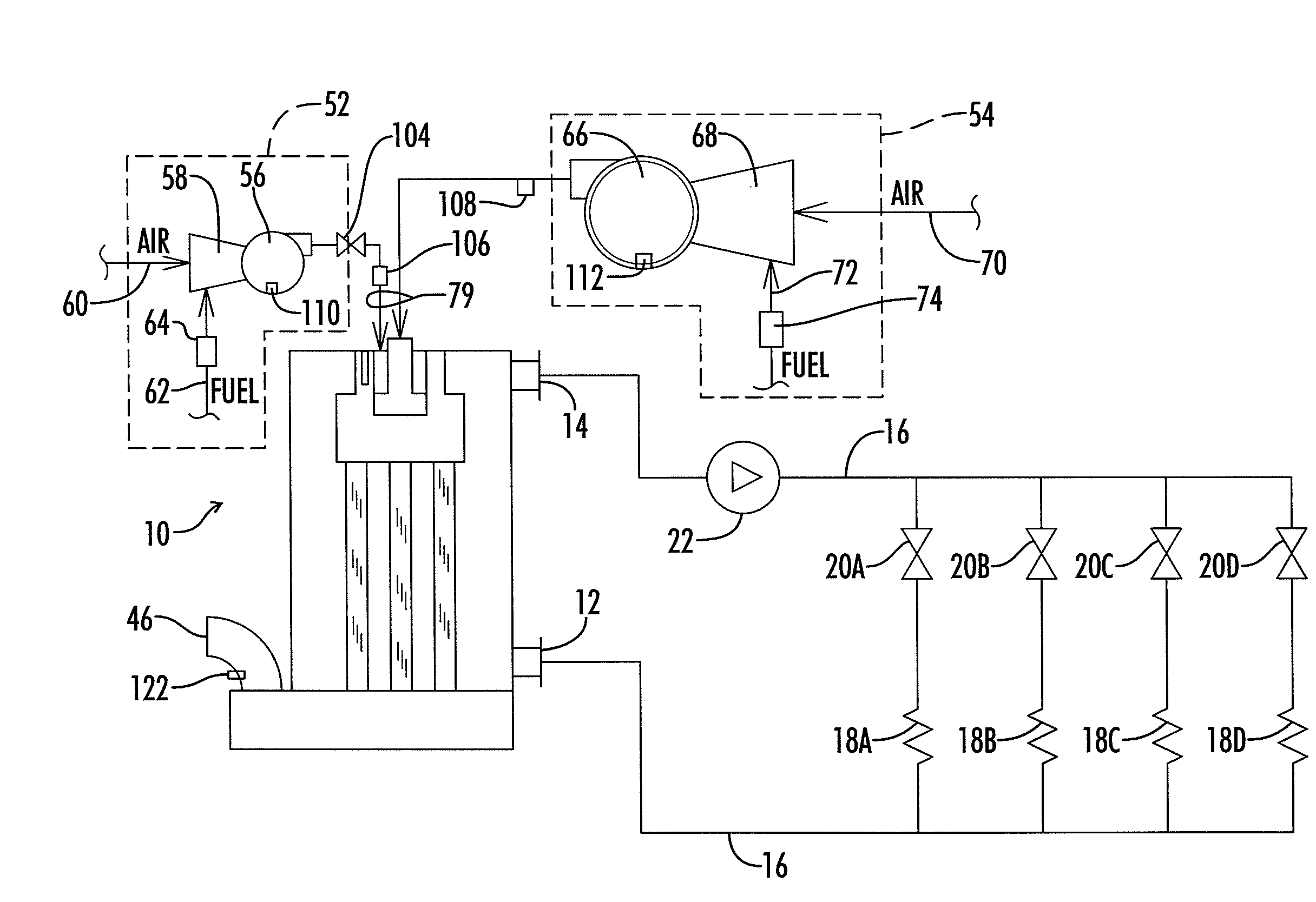
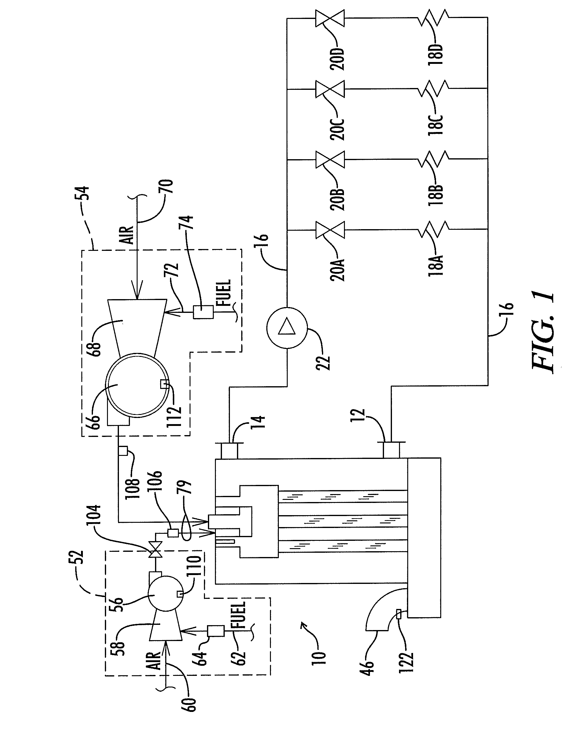
[0036]Referring now to the drawings, and particularly to FIG. 1, a water heating apparatus is shown and generally designated by the numeral 10. As used herein, the terms water heating apparatus or water heating appliance or water heater apparatus or water heater all are used interchangeably and all refer to an apparatus for heating water, including both hot water boilers and water heaters that do not actually “boil” the water. Such apparatus are used in a wide variety of commercial and residential applications including potable water systems, space heating systems, pool heaters, process water heaters, and the like. Also, the water being heated can include various additives such as antifreeze or the like.

[0037]The water heating apparatus 10 illustrated in FIG. 1 is a fire tube heater. A fire tube heater is one in which the hot combustion gases from the burner flow through the interior of a plurality of tubes. Water which is to be heated flows around the exterior of the tubes. The ope...


PUM


Abstract

A dual chamber burner assembly is provided for use with a heater apparatus having dual combustion air premix blowers. The burner assembly includes first and second interior zones communicated with first and second foraminous outer wall portions. First and second fuel and air inlet passages are communicated with the first and second interior zones, respectively.

Description

[0001]This is a continuation-in-part of U.S. patent application Ser. No. 12 / 252,841 filed Oct. 16, 2008, by Jim C. Smelcer, titled “Gas Fired Modulating Water Heating Appliance With Dual Combustion Air Premix Blowers”, and assigned to the assignee of the present invention.BACKGROUND OF THE INVENTION[0002]1. Field of the Invention[0003]The present invention relates generally to a single burner assembly with separate integrated chambers, and more particularly, but not by way of limitation, to such a burner which is especially suited for use with high capacity water heating appliances wherein it is desired to obtain high turndown ratios with respect to burner modulation.[0004]2. Description of the Prior Art[0005]Most conventional water heating appliance technologies utilize a single chamber burner designed to operate at a fixed flow rate of combustion air and fuel gas to the burner. Such technologies require that the appliance cycles on and off in response to a control system which mon...

Claims


Application Information

Patent Timeline
Patent Type & Authority Applications(United States)
IPC IPC(8): F24H1/40F23Q7/06
CPCF23D14/02F23D2203/1012F24H1/287F24H8/00F24H9/0036F24H9/2035Y02B30/102Y02B30/00F24H15/116F24H15/219F24H15/31F24H15/20F24H15/204F24H15/212F24H15/215F24H15/36F24H15/235F24H15/242F24H15/35
Inventor SMELCER, JIM C.
Owner LOCHINVAR
Learn More