
Fluid storage and dispensing systems and processes

Inactive Publication Date: 2010-05-06
ADVANCED TECH MATERIALS INC
View PDF29 Cites 140 Cited by
  • Summary
  • Abstract
  • Description
  • Claims
  • Application Information

AI Technical Summary

Benefits of technology

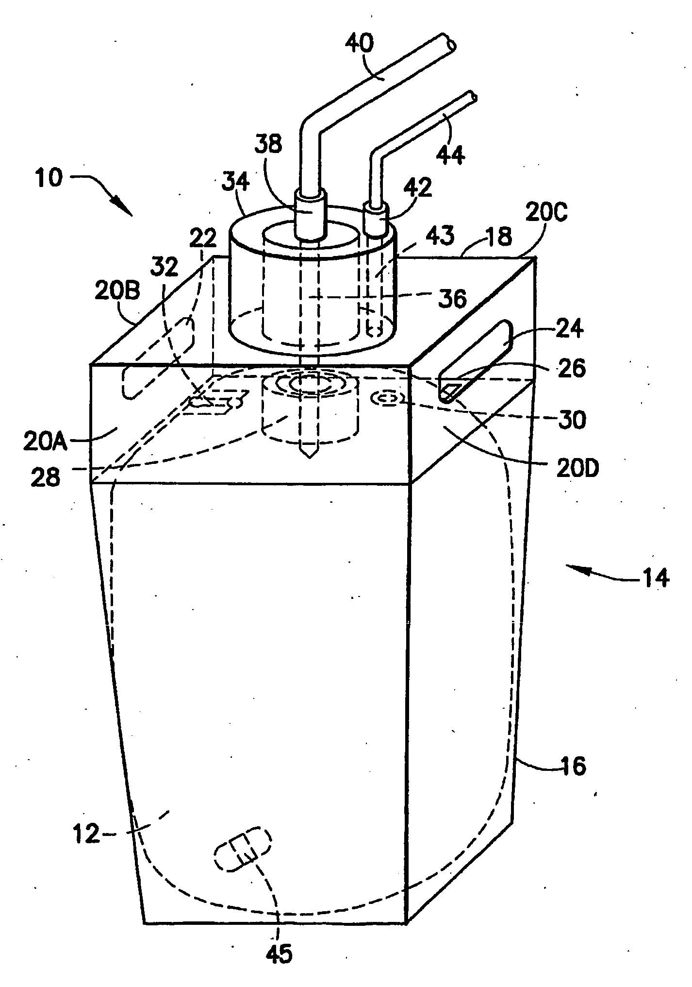
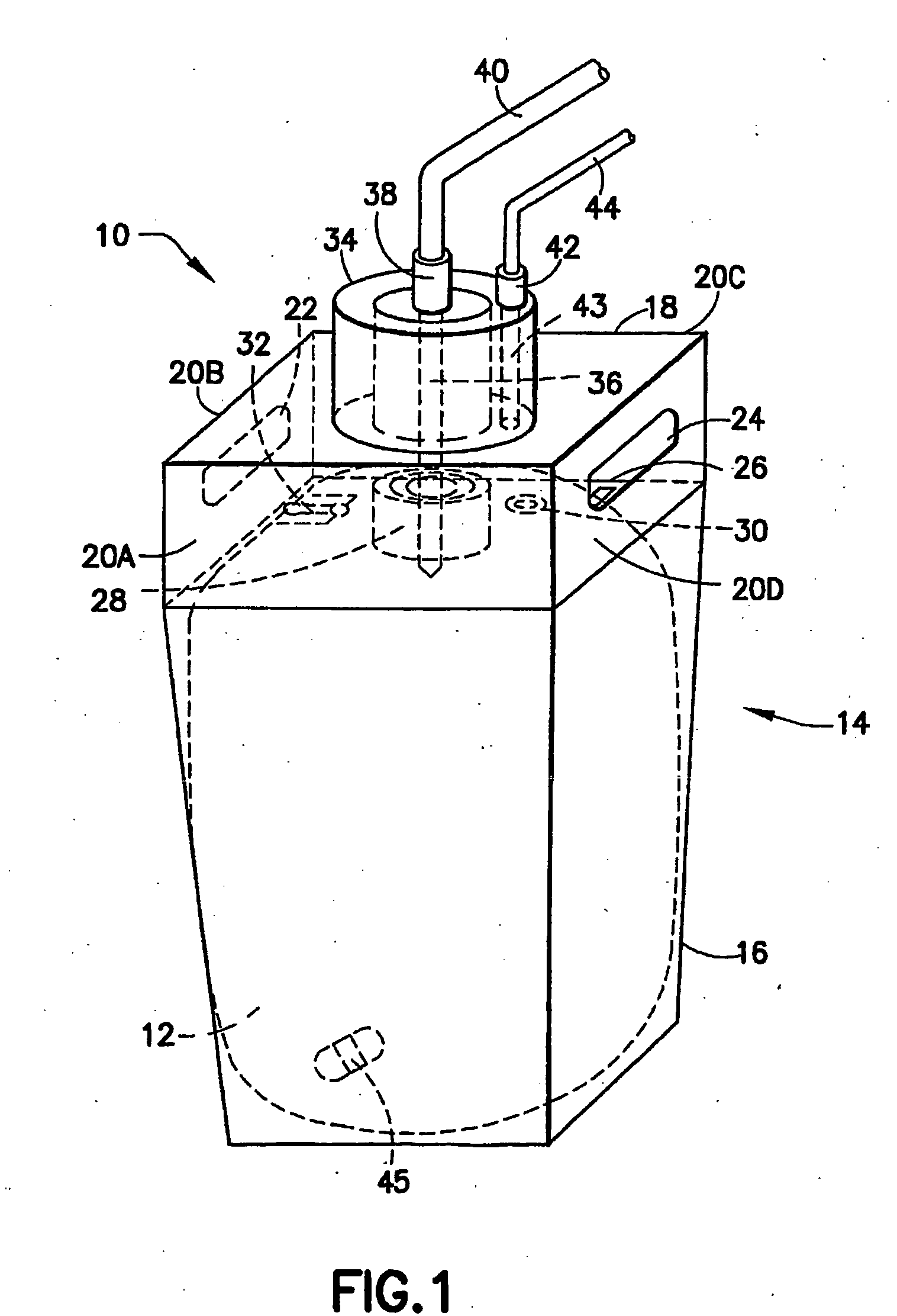
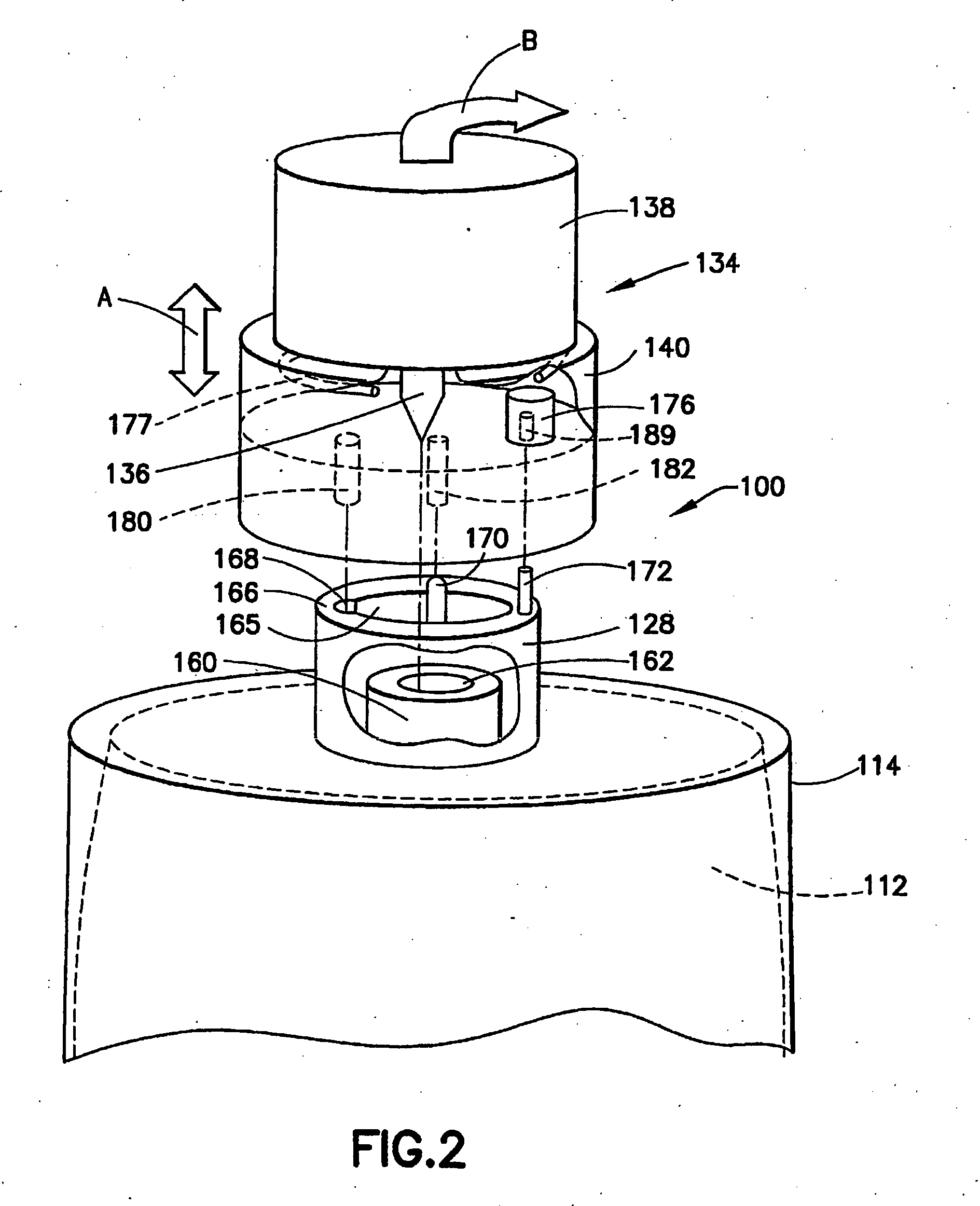
[0039]In a further embodiment, the invention relates to a fluid storage and dispensing system, including a fluid storage and dispensing vessel adapted for holding fluid in an interior volume thereof, said vessel having a port opening, a cap engaged with said port opening for sealing thereof, and a dispense assembly including a connector engageable with the cap, to access fluid in the vessel for dispensing thereof through the dispense assembly, such connector including at least one engagement member engageable with the cap to lockingly retain the connector in position for dispensing, and a manually graspable member coupled with at least one engagement member and manually translatable between a first biased position (down position) at which such at least one engagement member lockingly retains the connector in position for dispensing, and a second release position (up position) at which such at least one engagement member is disengaged from the cap to prevent removal of the connector from the cap.
[0049]Still another aspect of the invention relates to a fluid storage and dispensing package, comprising a container including a port, a liner in said container adapted for holding fluid, a fitment including an opening for fluid egress, coupled to said liner and to said port, and a cap adapted for engagement with said port, wherein said cap is additionally adapted for engagement with a dispensing assembly including a dispense connector adapted to cooperatively overfit the cap for withdrawal of fluid from the liner when pressure is exteriorly exerted on said liner, said dispense connector being adapted for connection to pressurizing gas for flow of the pressurizing gas into the container for exterior exertion of pressure on liner, a gas seal element positioned between the cap and the fitment to seal against the pressurizing gas in the container, and a plug seal to prevent fluid escape from the liner at the fitment.

Problems solved by technology

The fluid in such application in many instances is costly in character, and / or deleterious in effect if mis-dispensed.
Mis-dispensing of the fluid additionally may impair, or even render useless, a semiconductor device that is being manufactured.
Further, many chemical reagents used in semiconductor manufacturing are very hazardous in character, e.g., being toxic, pyrophoric, corrosive or otherwise harmful in exposure to persons or processing equipment.
An intrinsic problem with such coupling of supply vessel and dispensing assembly is that an incorrect coupling, i.e., connection of a wrong dispensing assembly to a supply vessel, results in contamination when the sealing membrane on the package is punctured by the dip tube of the dispense head, and it then is discovered that a wrong dispensing assembly has been utilized.
This can occur even if the mis-connection is immediately discovered, e.g., by inability to engage the dispensing assembly with any complementary connection structure on the fluid package.
Another issue of significance in the use of liner-based fluid storage and dispensing packages of the above-describe type, is the need to dispense as much of the fluid contents of the liner as possible, so that the fluid, which as discussed above may be costly in character, is efficiently utilized, without significant amounts of fluid being left in the liner at the conclusion of the dispensing operation.
Although small in volume, this headspace gas is deleterious to the contained fluid.
A primary disadvantage of the headspace gas is that when the liner is subjected to external pressure in the dispensing operation, the resultingly compressed headspace gas solubilizes in the contained fluid to produce dissolved gas therein, in accordance with Henry's Law.
This liberation of dissolved gas causes irregular and variable dispense profiles of the chemical reagent, e.g., a photoresist that is being flowed to a semiconductor manufacturing tool in a semiconductor manufacturing operation, resulting in the formation of potentially severe wafer defects, bubble formation on surfaces and subsequent popping of such bubbles, etc.
Thus, the presence of significant headspace in the liner entails significant adverse consequences along the entire extent of the fluid delivery path including the final use of the fluid in the process system.
In the dispensing of liquid from a liner-based package containing headspace gas, the exhaustion of fluid from the liner causes headspace gas to be drawn into the suction train of the dispensing flow circuitry, and this entrainment of headspace gas results in the appearance of bubbles in the downstream liquid flow.
The “first bubble” sensing method of empty detection has proven reliable, but is associated with the inherent disadvantages of headspace gas becoming solubilized in the liquid in the liner and subsequently being released from the liquid during the dispensing operation, since such efflux of gas may give a premature indication of exhaustion of liquid from the liner, thereby preventing maximum utilization of liquid from the liner from being achieved, as well as interfering with the operation of downstream process equipment.
Users having small hands generally experience difficulty in this disassembly procedure, particularly in pressing in the pivot clamps.
Additionally, it is very difficult to break the static seal of the O-rings.
These factors, taken together, adversely impact the ease of use of such liner-based fluid storage and dispensing packages.
Further, considering the shortcomings involved in prior use of liner-based fluid storage and dispensing packages, various problems are encountered with so-called breakseal or membrane elements that are pierced by the probe of the dispensing assembly when the connector is brought into engagement with the cap of the vessel.
First, breaking through the currently employed breakseal with the dispense probe produces particles that are carried into the contained chemical by the probe, thereby compromising the purity of the contained fluid.
Second, the currently employed breakseal does not allow for material changes to match the needs of the chemical in the liner.
Third, the currently employed breakseal does not allow vessels to be easily resealed for disposal.
Fourth, the currently employed breakseal requires high force to insert the probe connector assembly, since the probe must pierce the membrane seal, which may entail resistance to the engagement of the connector with the vessel.
Fifth, the seal integrity of the currently employed breakseal can be compromised by plastic creep induced relaxation of the seal clamping force.
In some instances, due to inadequate training or accident, caps are unscrewed from containers with the probe still installed.
This creates difficulties in removing the cap from the probe body and exposes the probe to contaminants, as well as providing the potential for subsequent mis-connection if the probe body and attached cap are then coupled with another container.
A further deficiency associated with the cap utilized in current liner-based fluid storage and dispensing packages relates to the pressurization opening in the cap, through which pressurizing gas is introduced into the vessel containing the liner, to exert pressure on the exterior surface of the liner, and thereby achieve pressure-mediated dispensing of fluid contained in the liner.
Such pressurization opening in the cap is sealed by a tear tab, and removal of the tear tab to expose the opening for gas introduction frequently produces rough edges at the pressurization opening, due to the tear tab removal process.
These rough edges in turn cause leaks to the O-ring seal of the dispense nozzle of the dispensing assembly.
In some instances of use of keycoded caps and probes in liner-based fluid storage and dispensing systems, users have been known to switch caps in order to defeat the keycode system, and occurrence that could lead to damage or destruction of products manufactured using fluid from such systems.
Such necessity may result from an incorrect keycoding of a fluid reagent by a chemical supplier, or performance of specialty chemical and process trials in which keycodes are not assigned, or accidental damage to a cap requiring its replacement.

Method used


Image

  • Fluid storage and dispensing systems and processes
  • Fluid storage and dispensing systems and processes
  • Fluid storage and dispensing systems and processes

Examples


example 1

[0305]A test was run to determine the efficacy of a pressure transducer for empty detect monitoring in pressure-mediated dispensing of fluid from a liner-based fluid storage and dispensing system of a general type as described in connection with FIG. 3 hereof, to determine the suitability of a specific liner-based fluid storage and dispensing package for dispensing photoresist as part of a dispense train including a downstream dispenser having a process filter upstream thereof. As used in such context, the term “downstream dispenser” refers to process equipment that is associated with a fluid-utilizing tool to supply fluid to the tool in a predetermined amount or at a predetermined rate. The downstream dispenser made for example include a final dispense pump, e.g., a compressible tube pump, or a flow-metering device, injector, ejector, compressor, the lower, spray head, nozzle, etc.

[0306]The dispensing operation in this application must supply the required photoresist flow through t...


PUM

PropertyMeasurementUnit
Thicknessaaaaaaaaaa
Thicknessaaaaaaaaaa
Angleaaaaaaaaaa

Abstract

Fluid storage and dispensing systems and processes involving various devices, structures and arrangements, as well as techniques and methods, for fluid storage and dispensing, including, without limitation, pre-connect verification couplings that are usefully employed in application to fluid storage and dispensing packages, to ensure proper coupling and avoid fluid contamination issues, empty detect systems that are usefully employed for fluid storage and dispensing packages incorporating liners that are pressure-compressed in the fluid dispensing operation, ergonomically enhanced structures for facilitating removal of a dispense connector from a capped vessel, cap integrity assurance systems for preventing misuse of vessel caps, and keycoding systems for ensuring coupling of proper dispense assemblies and vessels. Fluid storage and dispensing systems are described, which achieve zero or near-zero headspace character, and prevent or ameliorate solubilization effects in liquid dispensing from liners in overpack vessels.

Description

BACKGROUND OF THE INVENTION[0001]1. Field of the Invention[0002]The present invention relates to fluid storage and dispensing systems and processes. Aspects of the invention, hereinafter disclosed, relate to various devices, structures and arrangements, as well as processes and methods, for fluid storage and dispensing, and include, without limitation, pre-connect verification couplings that are usefully employed in application to fluid storage and dispensing packages, to ensure proper coupling and avoid fluid contamination issues, empty detect systems that are usefully employed for fluid storage and dispensing packages incorporating liners that are pressure-compressed in the fluid dispensing operation, ergonomically enhanced structures for facilitating removal of a dispense connector from a capped vessel, cap integrity assurance systems for preventing misuse of vessel caps, and keycoding systems for ensuring coupling of proper dispense assemblies and vessels.[0003]2. Description of...

Claims


Application Information

Patent Timeline
IPC IPC(8): H01L21/30B67D7/06B65D35/56B67D7/10B65D83/00G05D7/00B67D7/00B65D17/34B65D41/06B23P19/04B23P11/00B67D99/00
CPCB67D7/0261B67D7/0288B67D7/32B67D7/344B67D7/34Y10T29/49826F16L37/08B67D7/3281Y10T29/53B67D1/08B67D7/3227F16K35/00F16K35/025
Inventor O'DOUGHERTY, KEVIN T.TOM, GLENN M.
Owner ADVANCED TECH MATERIALS INC
Learn More