
Method and System for Detecting Corrosion Under Insulation

a technology of corrosion detection and insulation, applied in the field of thermal imaging systems, can solve the problems of shortening the lifespan of expensive industrial infrastructure, increasing the corrosion attack, and affecting the efficiency of industrial infrastructure,

Active Publication Date: 2010-05-06
HONEYWELL INT INC
View PDF12 Cites 30 Cited by
  • Summary
  • Abstract
  • Description
  • Claims
  • Application Information

AI Technical Summary

Benefits of technology

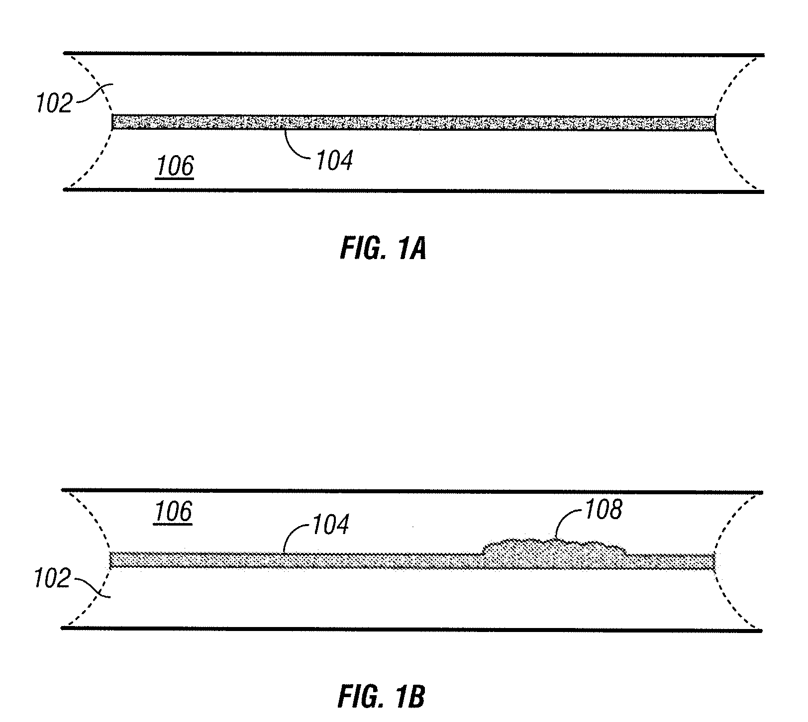
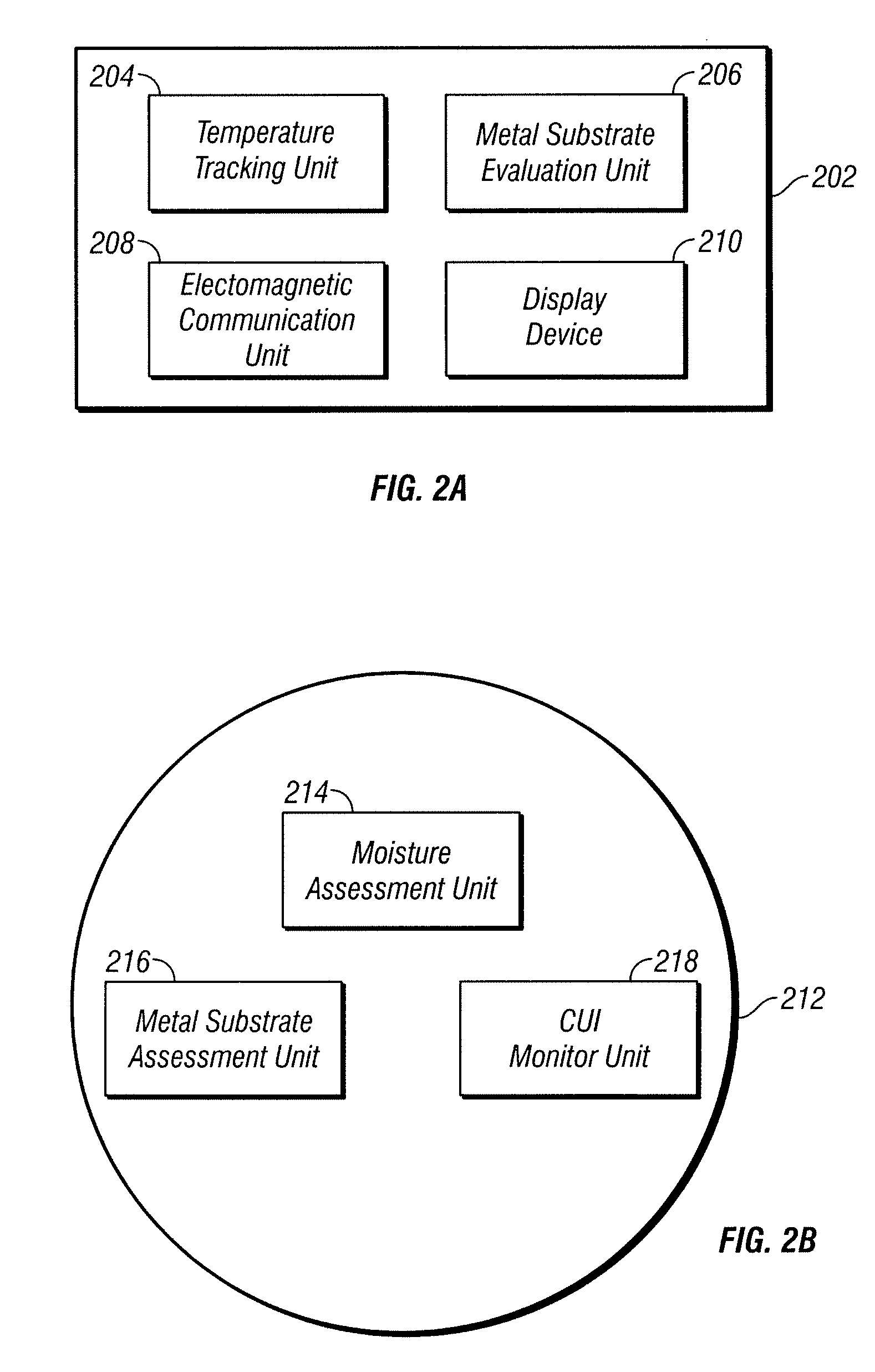
[0006]A method of detecting corrosion under insulation is provided, the method including at least the steps of: disposing one or more thermal imaging devices in electromagnetic communication with an insulated substrate; obtaining corrosion related data by means of the thermal imaging devices; and communicating the corrosion related data to an operator.
[0007

Problems solved by technology

Temperature gradients at the metal surface can lead to concentration of corrosive species, for example salts, which will accelerate the corrosion attack.
Regardless of how securely insulation materials are applied to a substrate material, there will inevitably be areas where fluids can seep in, and where temperature gradients exist, thereby creating conditions that subsequently causes corrosion and damage to the substrate.
Detection of CUI in industrial plants has been identified as a significant problem, which can affect the integrity of tanks and pipes and lead to a shortening of the lifespan or even outright failure of expensive industrial infrastructure.
Lengthy inspections and equipment failures often lead to manufacturing facility downtime, and consequently a loss of efficiency and increase in associated costs.
CUI can be especially problematic wherever mastic is used as a finish, as well as around seals and metal ductwork, and wherever prior mechanical damage has occurred.
One insidious aspect of CUI is that the corrosion is hidden from view by the thermal insulation.
It is neither practical nor economical to remove the insulation at all locations for direct inspection.
However, the accuracy of this equipment has been insufficient and costly due to “false calls,” which result in added expense due to the downtime associated with unnecessary removal and inspection of thermal insulation.

Method used


Image

  • Method and System for Detecting Corrosion Under Insulation
  • Method and System for Detecting Corrosion Under Insulation
  • Method and System for Detecting Corrosion Under Insulation

Examples


Embodiment Construction

[0012]The description that follows includes exemplary systems, methods, and techniques that encompass several different embodiments of the presently inventive subject matter. However, it will be understood by those of ordinary skill in the pertinent arts that the disclosed embodiments may be practiced in the absence of one or more of the specific details described herein. In other instances, well-known manufacturing equipment, protocols, structures and techniques have not been shown or described in detail in order to avoid obfuscation in the description.

[0013]Embodiments of the inventive subject matter integrate equipment, automation, and algorithms to form a method for identifying wet thermal insulation by scanning multiple locations along insulated piping, tanks, or other manufacturing equipment. In various embodiments, such scans can occur individually, sequentially, or simultaneously, with the results then being stored and comparatively analyzed.

[0014]Further embodiments compris...


PUM


Abstract

The present invention relates generally to thermal imaging systems and methods and uses therefor, and in a particular though non-limiting embodiment, to a method of detecting corrosion under insulation, as well as corrosion-related material data associated therewith. The system utilizes advanced infrared imaging video cameras to detect characteristic signatures of wet thermal traits on process equipment. Various embodiments of the invention integrate equipment, automation, and algorithms to form a method for identifying wet thermal insulation by scanning multiple locations along insulated piping, tanks, or other manufacturing equipment. Such scans can occur individually, sequentially, or simultaneously, with the results then being stored and comparatively analyzed. Further embodiments comprise tracking the approximate time of exposure to moisture, prediction of the corrosion rates for underlying insulated metal substrates, and measuring wall thicknesses along either predetermined random portions of the metal substrate.

Description

FIELD OF THE INVENTION[0001]The present invention relates generally to thermal imaging systems and methods and uses therefor, and in a particular though non-limiting embodiment, to a method of detecting corrosion under insulation, as well as corrosion-related material data associated therewith.BACKGROUND OF THE INVENTION[0002]Corrosion under insulation (CUI) is corrosion that develops over time beneath thermal insulation used on pipes, tanks and other manufacturing and process equipment. Wherever piping, tanks or equipment are thermally insulated, there is potential for CUI. It is usually caused by condensation, rainwater, cleaning fluids, etc., that permeate into the insulation and attack the substrate to which it is applied. Impurities in the atmosphere and temperature gradients between tubulars and associated insulation also play a role in CUI development. Temperature gradients at the metal surface can lead to concentration of corrosive species, for example salts, which will acce...

Claims


Application Information

Patent Timeline
IPC IPC(8): G01N29/02
CPCG01N25/72
Inventor KANE, RUSSELL D.COHEN, ISAACMIEZIANKO, ROLANDEDEN, DAVID A.
Owner HONEYWELL INT INC
Learn More