
Method of Curing Color Filter for Electronic Display Using Electron-Beam and Method of Fabricating Color Filter for Electronic Display Using the Same

Inactive Publication Date: 2010-04-29
HOSEO UNIV ACADEMIC COOP FOUND
View PDF0 Cites 2 Cited by
  • Summary
  • Abstract
  • Description
  • Claims
  • Application Information

AI Technical Summary

Benefits of technology

[0032]A further aspect of the present invention is to provide a polymerization condition and technique than enables electron-beam curing to be effectively applied to a color filter having a thickness of about 1.5 μm.

Problems solved by technology

However, the plastic substrate is very vulnerable to heat, and provides many restrictions in fabrication of the color filter.
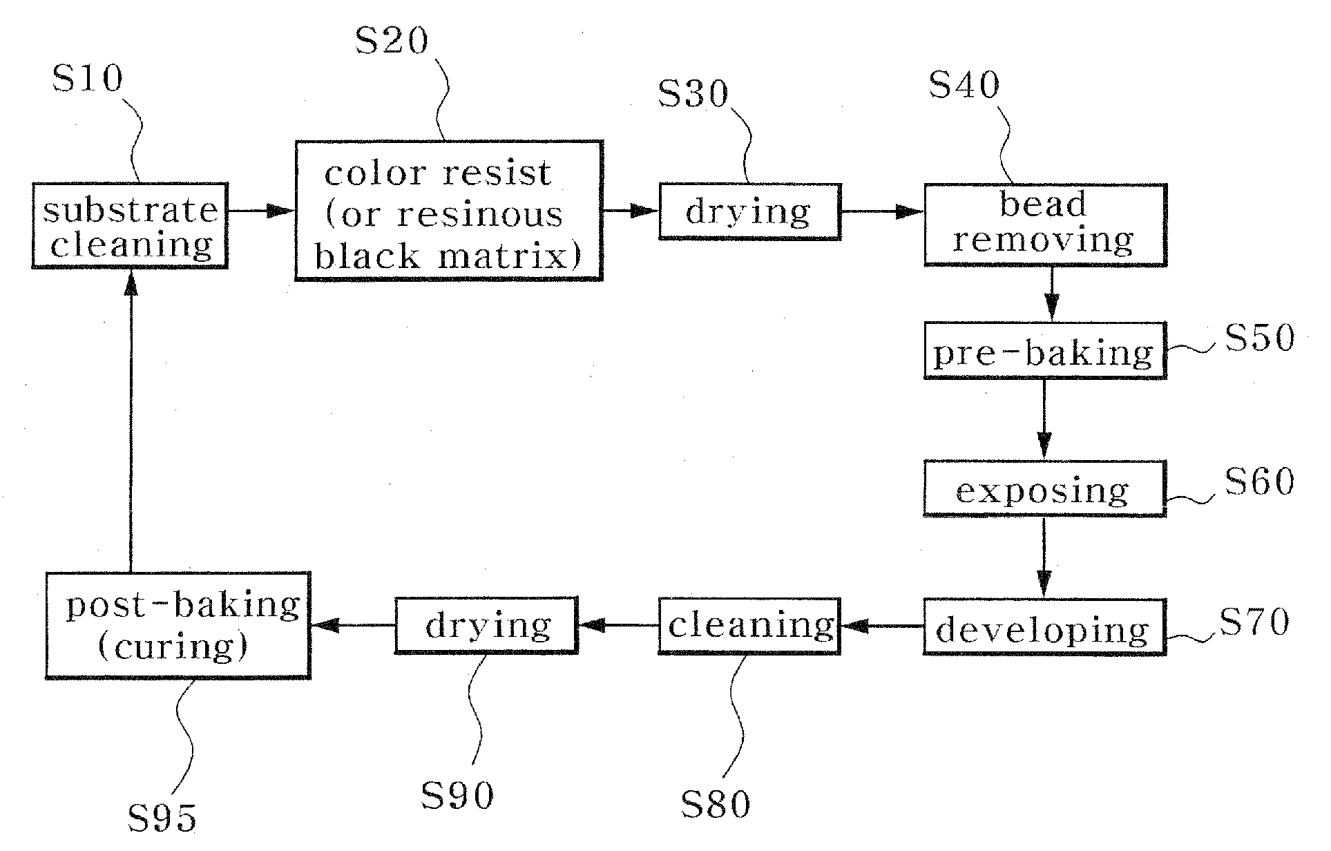
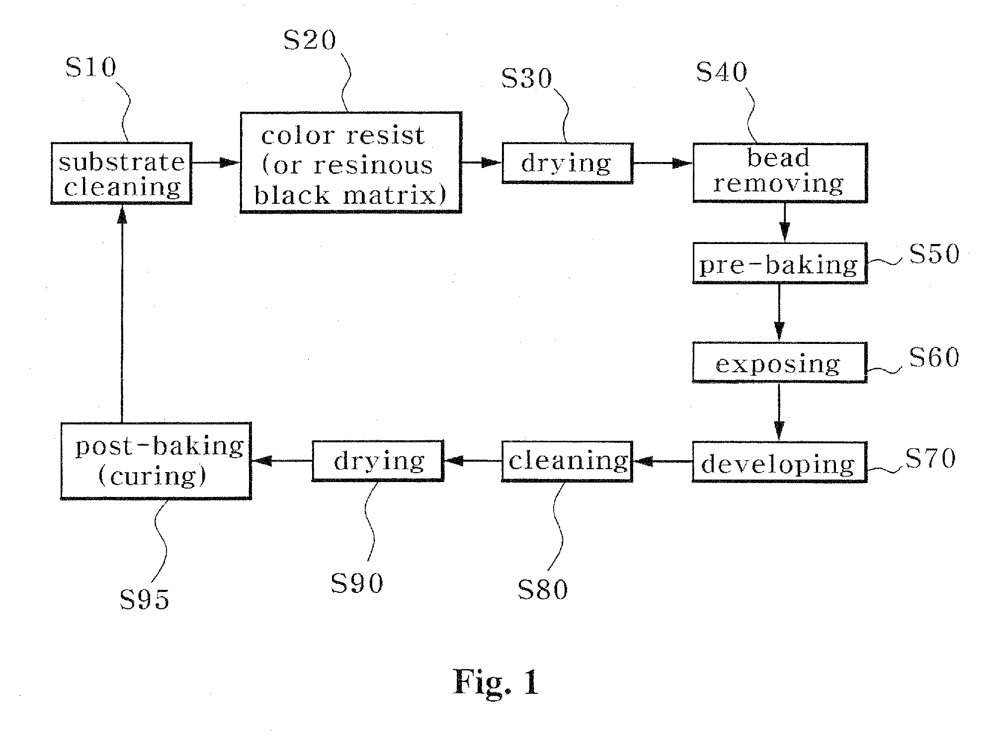
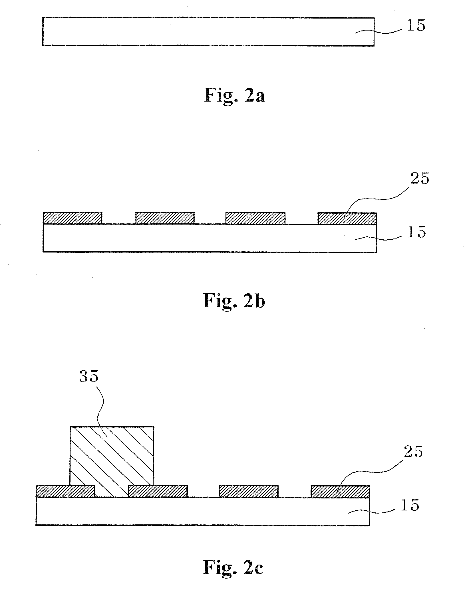
As described in FIG. 1 or FIGS. 2 to 2e, since the substrate is heated at about 200° C., the plastic substrate is deformed due limitations in terms of physical and mechanical properties, thereby making it difficult to achieve dimension control of the color filter module and precision of a fine pattern.
Furthermore, the curing process using ultraviolet rays and heat requires additives such as a photo-initiator in addition to a binder resin and a cross-linkable monomer for forming the color patterns, thereby deteriorating production efficiency.
Thus, it is necessary to have a process of controlling the added amount of photo-initiator, which can cause deterioration of the production efficiency.
As described above, when UV or heat is used for the curing process in fabrication of the color filter on the plastic substrate for flexible displays, the limits in terms of physical and mechanical properties of the plastic substrate cause deformation of the plastic substrate, and make it difficult to control the dimensions of the color filter module and to achieve precision of a fine pattern.
Furthermore, the photo-initiator must be used to achieve UV or thermal polymerization, thereby deteriorating production efficiency.

Method used


Image

  • Method of Curing Color Filter for Electronic Display Using Electron-Beam and Method of Fabricating Color Filter for Electronic Display Using the Same
  • Method of Curing Color Filter for Electronic Display Using Electron-Beam and Method of Fabricating Color Filter for Electronic Display Using the Same
  • Method of Curing Color Filter for Electronic Display Using Electron-Beam and Method of Fabricating Color Filter for Electronic Display Using the Same

Examples


example 1

Curing by Electron Beam Irradiation to a Color Filter Sample on a Glass Substrate

[0111](1) Step 1 in Example 1: Coating and Drying a Color Filter on the Glass Substrate

[0112]As in a typical method of fabricating a color filter, a resist for forming a red color filter provided as a color filter sample was coated to a thickness of 1.5 μm and dried on a glass substrate (Corning 1730, 0.7 mm in thickness).

[0113]FIG. 12 is an SEM image of the color filter sample coated to a thickness of 1.5 μm in this example.

[0114]Next, Fourier transform infrared spectroscopy (FT-IR) was used for analysis before irradiation of an electron beam.

[0115]FIGS. 13 and 14 are graphs depicting FT-IR analysis results on color filter resist samples of Dongwoo Fine-Chemicals Co. Ltd., Korea, and JSR Co. Ltd., Japan.

[0116]Herein, since the color filter resists of Dongwoo Fine-Chemicals Co. Ltd., Korea and JSR Co. Ltd, Japan are representative color filters in the art, they were adopted and compared. Hence, if all o...

example 2

Electron Beam Irradiation From the Rear Side of the Glass Substrate

[0130]An electron beam having a curing energy of 1 MeV was irradiated at a total irradiation amount of 100 kGy to the color filter samples prepared as in Example 1 from the rear side of the glass substrate to adjust the energy of the electron beam as shown in FIG. 11.

[0131]FIG. 16 is a graph depicting an FT-IR analysis result on color filter sample TR-PI when the electron beam was irradiated from the rear side of the glass substrate.

[0132]In FIG. 16, absorption peaks of the acrylate cross-linkable monomer, 807 cm−1 and 1405 cm−1, are not substantially observed.

example 3

Electron Beam Curing of Color Filters Coated on a Glass Substrate (Effect Dependent on Irradiation Amount of Electron Beam)

[0141]With color filter samples coated on the glass substrate under the same conditions as Example 1, a total irradiation amount of electron beam was varied from 20 to 50, 150 and 200 kGy in order to obtain an effective irradiation amount for polymerization. After irradiation of the electron beam, the polymerization degrees of the color filter samples were analyzed based on FT-IR.

[0142]FIG. 19 is a graph depicting an FT-IR analysis result on curing degrees of color filter samples after irradiating an electron-beam according to a condition of Example 3.

[0143]Referring to FIG. 19, it can be seen that the most effective condition for polymerization of the color filter was obtained at about 50˜100 kGy (T3-PI-20, T3-PI-50), and that the polymerization degree was not significantly increased at 100 kGy or more (T3-PI-150, T3-PI-200). For color filter sample T3-PI-20 at...


PUM


Abstract

Disclosed herein is a method of curing a color filter for an electronic display using an electron beam at low temperature. A conventional method of curing the color filter by thermal-heating is not suitable for a process of fabricating next generation flexible displays. In the method of the invention, after a color resist pattern is formed on a substrate, the resist is cured by an electron beam at 100° C. or less. Hence, the method can minimize damage of the substrate while facilitating dimension control of the color pattern and achieving precision of a fine pattern. A method of fabricating a color filter for an electronic display using the method is also disclosed.

Description

CROSS-REFERENCE TO RELATED APPLICATION[0001]The present application claims the benefit under 35 U.S.C. §119 of Korean Patent Application No. 10-2008-0106109, filed Oct. 28, 2008, which is hereby incorporated by reference in its entirety.BACKGROUND OF THE INVENTION[0002]1. Field of the Invention[0003]The present invention relates to a method of curing a color filter for an electronic display using an electron beam at low temperature. The present invention relates to a technique that employs an electron beam for curing a color filter at low temperature instead of curing the color filter by thermal-heating as in the prior art.[0004]2. Description of the Related Art[0005]A color filter module is mainly used in the field of thin film transistor liquid crystal displays (TFT-LCDs) and plasma display panels (PDPs), and is also applied to white organic light emitting diodes (OLEDs) that include a color filter.[0006]In LCDs, PDPs or OLEDs, the color filter is generally produced by forming a b...

Claims


Application Information

Patent Timeline
IPC IPC(8): G03F1/00G02B5/20G02F1/1335
CPCG02B5/201G02B5/223G03F7/40G03F7/027G03F7/2037G03F7/0007G02B5/20
Inventor KIM, JEONG SEOGCHEON, CHAE ILCHO, JUNG MINLEE, KYOUNG HOHAN, YOUNG HWANLEE, BYOUNG CHEOL
Owner HOSEO UNIV ACADEMIC COOP FOUND
Learn More