
Method of coding a source audio signal, corresponding coding device, decoding method and device, signal, computer program products

Active Publication Date: 2009-03-26
FRANCE TELECOM SA
View PDF13 Cites 7 Cited by
  • Summary
  • Abstract
  • Description
  • Claims
  • Application Information

AI Technical Summary

Benefits of technology

[0035]An embodiment of the invention thus relies on a novel and inventive approach to the encoding of the coefficients of a source audio signal enabling the reduction of the bit rate allocated to the transmission of the quantization intervals while at the same time keeping an injected quantization noise profile that is as close as possible to the one given by a masking curve computed from full knowledge of the signal.
[0041]The technique of an embodiment of the invention results in improved efficiency of compression as compared with the prior art techniques, and therefore greater perceived quality.

Problems solved by technology

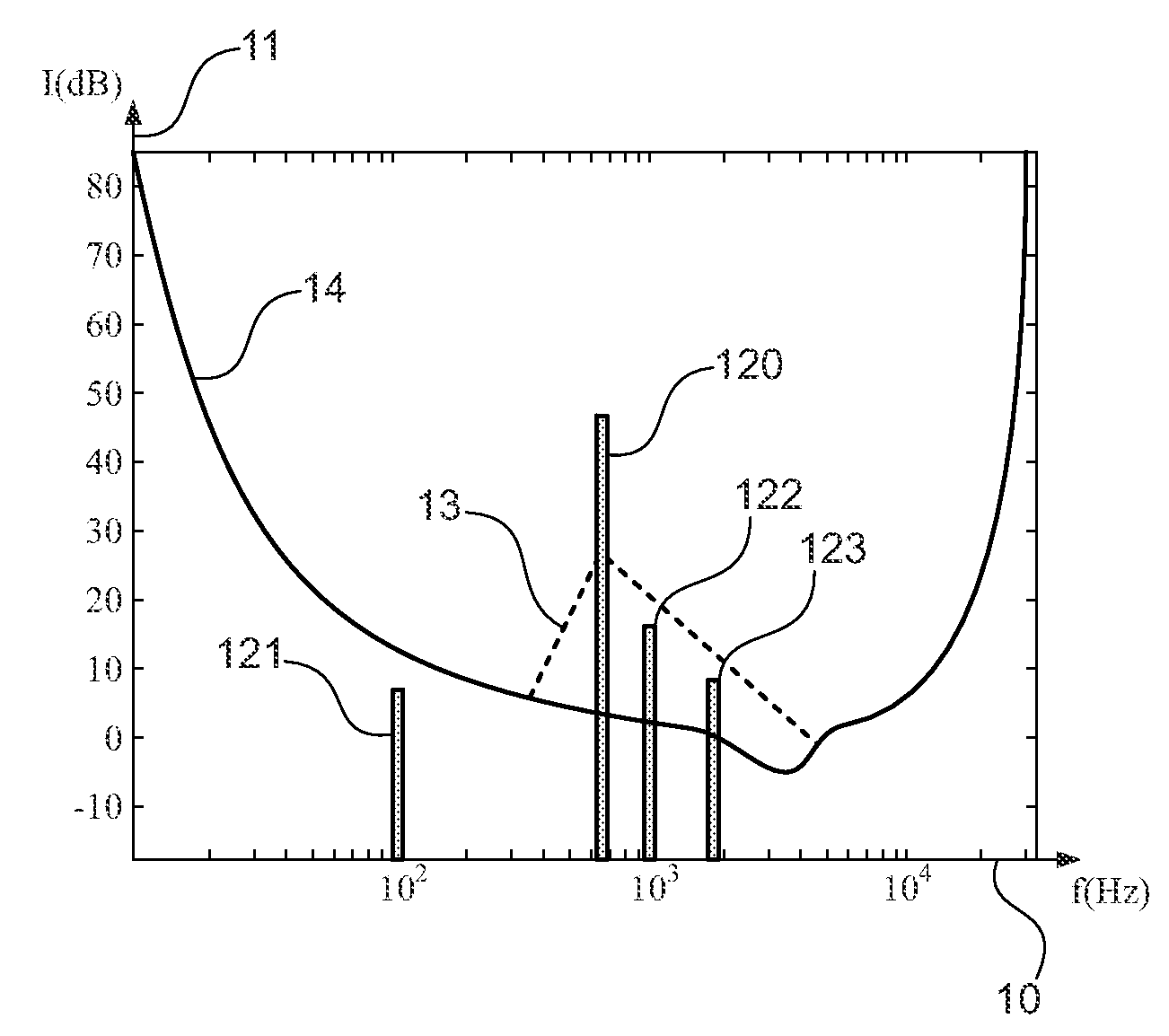
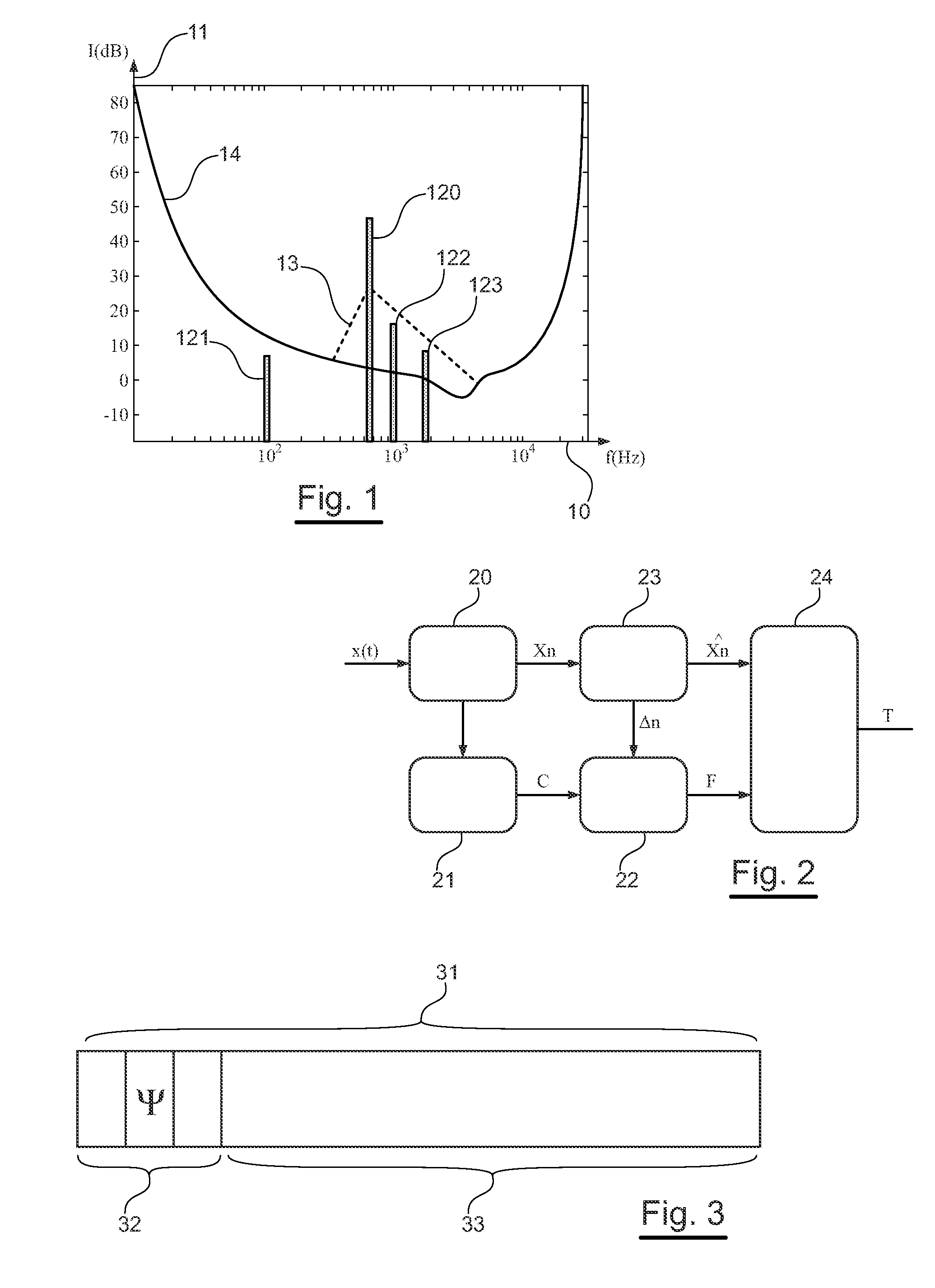
The human ear is incapable of separating two components of a signal emitted at proximate frequencies as well as in a limited time slot.
However, one drawback of perceptual transform encoding in a hierarchical approach of this kind lies in the fact that the scale factors obtained have to be transmitted from the very first level or basic level.
Indeed, the masking model implemented simultaneously in the encoder and the decoder is necessarily closed-ended, and can therefore not be adapted with precision to the nature of the signal.
Furthermore, the masking curves are computed on the assumption that the signal is a standing signal, and cannot be properly applied to the transient portions and to sonic attacks.
Furthermore, since the masking curves are obtained at each level from coefficients or residues of coefficients quantized at the previous levels, the masking curve for the first level is incomplete because certain portions of the spectrum have not yet been encoded.

Method used


Image

  • Method of coding a source audio signal, corresponding coding device, decoding method and device, signal, computer program products
  • Method of coding a source audio signal, corresponding coding device, decoding method and device, signal, computer program products
  • Method of coding a source audio signal, corresponding coding device, decoding method and device, signal, computer program products

Examples


Embodiment Construction

1. Structure of the Encoder

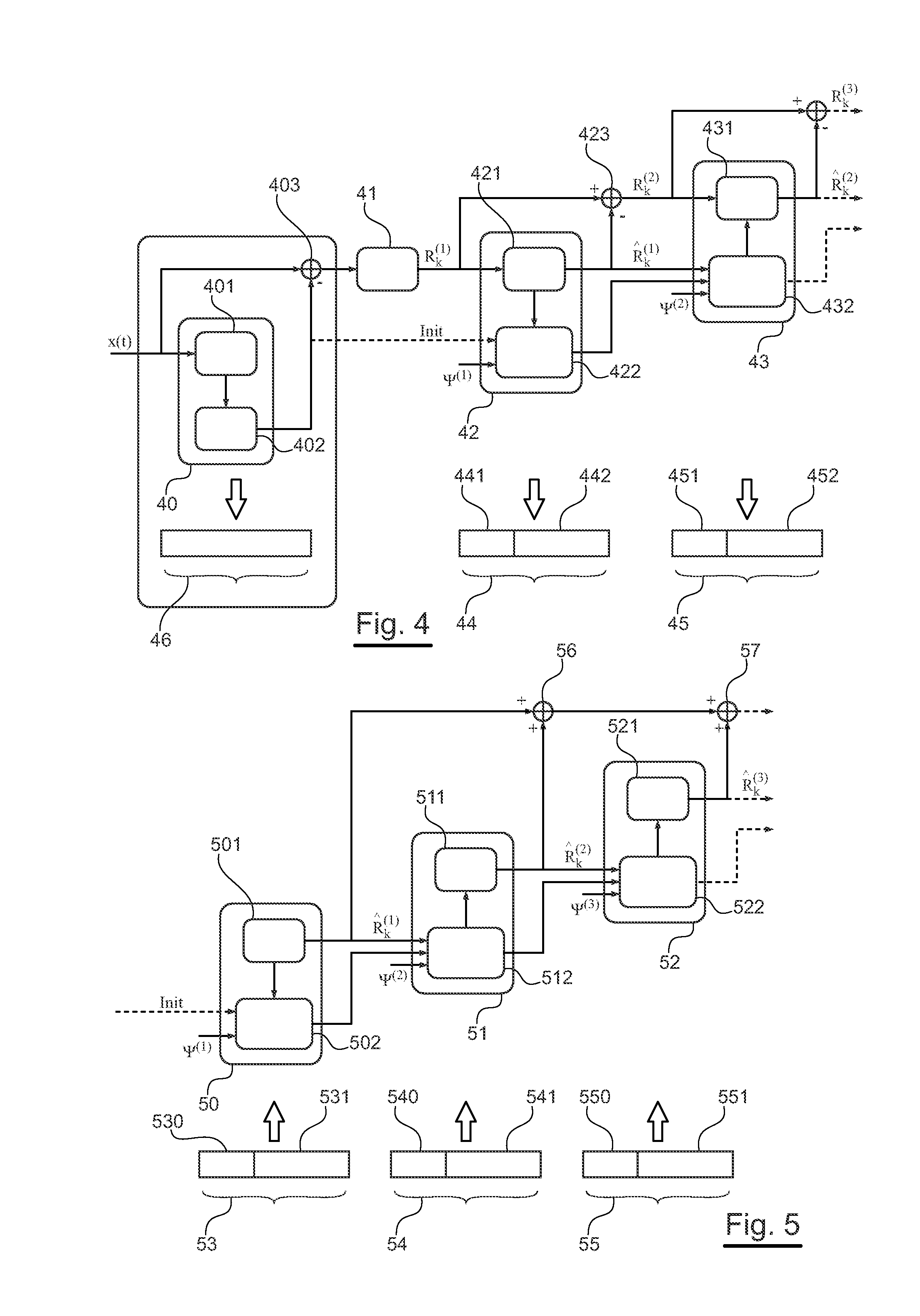
[0086]Here below, a description is provided of an embodiment of the invention in the particular application of hierarchical encoding. It may be recalled that, in this scheme, the hierarchical encoding sets up a cascading of the perceptual quantization intervals at output of a time-frequency transform (for example a modified discrete cosine transform or MDCT) of the source audio signal to be encoded.

[0087]An encoder according to this embodiment of the invention is described with reference to FIG. 4. A source audio signal x(t) is to be transformed in the frequency domain, directly or indirectly. Indeed, optionally, the signal x(t) may first of all be encoded in an encoding step 40. A step of this kind is implemented by a “core” encoder. In this case, this first encoding step corresponds to a first hierarchical encoding level, i.e. the basic level. A “core” encoder of this kind can implement an encoding step 401 and a local decoding step 402. It then delivers...


PUM


Abstract

A method is provided for coding a source audio signal. The method includes the following steps: coding a quantization profile of coefficients representative of at least one transform of the source audio signal, according to at least to distinct coding techniques, delivering at least two sets of data representative of a quantization profile; selecting one of the sets of data representative of a quantization profile, as a function of a predetermined selection criterion; transmitting and / or storing the set of data representative of a selected quantization profile and an indicator representative of the corresponding coding technique.

Description

CROSS-REFERENCE TO RELATED APPLICATIONS[0001]This Application is a Section 371 National Stage Application of International Application No. PCT / FR2007 / 050915, filed Mar. 12, 2007 and published as WO 2007 / 104889 on Sep. 20, 2007, not in English.STATEMENT REGARDING FEDERALLY SPONSORED RESEARCH OR DEVELOPMENT[0002]None.THE NAMES OF PARTIES TO A JOINT RESEARCH AGREEMENT[0003]None.FIELD OF THE DISCLOSURE[0004]The field of the disclosure is that of the encoding and decoding of audio-digital signals such as music or digitized speech signals.[0005]More particularly, the disclosure relates to the quantization of the spectral coefficients of audio signals, in implementing perceptual encoding.[0006]The disclosure can be applied especially but not exclusively to systems for the hierarchical encoding of audio-digital data, using a scalable data encoding / decoding type system, proposed in the context of the MPEG Audio (ISO / IEC 14496-3) standard.[0007]More generally, the disclosure can be applied in...

Claims


Application Information

Patent Timeline
IPC IPC(8): H04B1/66G10L19/02G10L19/035
CPCG10L19/035
Inventor PHILIPPE, PIERRICKVEAUX, CHRISTOPHECOLLEN, PATRICE
Owner FRANCE TELECOM SA
Learn More