
Magnetic head and method of producing the same

Inactive Publication Date: 2008-04-03
FUJITSU LTD
View PDF7 Cites 2 Cited by
  • Summary
  • Abstract
  • Description
  • Claims
  • Application Information

AI Technical Summary

Benefits of technology

[0010]An object of the present invention is to provide a magnetic head including a CPP type read-head, which is capable of effectively applying a bias magnetic field of a hard magnetic layer to the read-head so as to improve and stabilize detection performance.
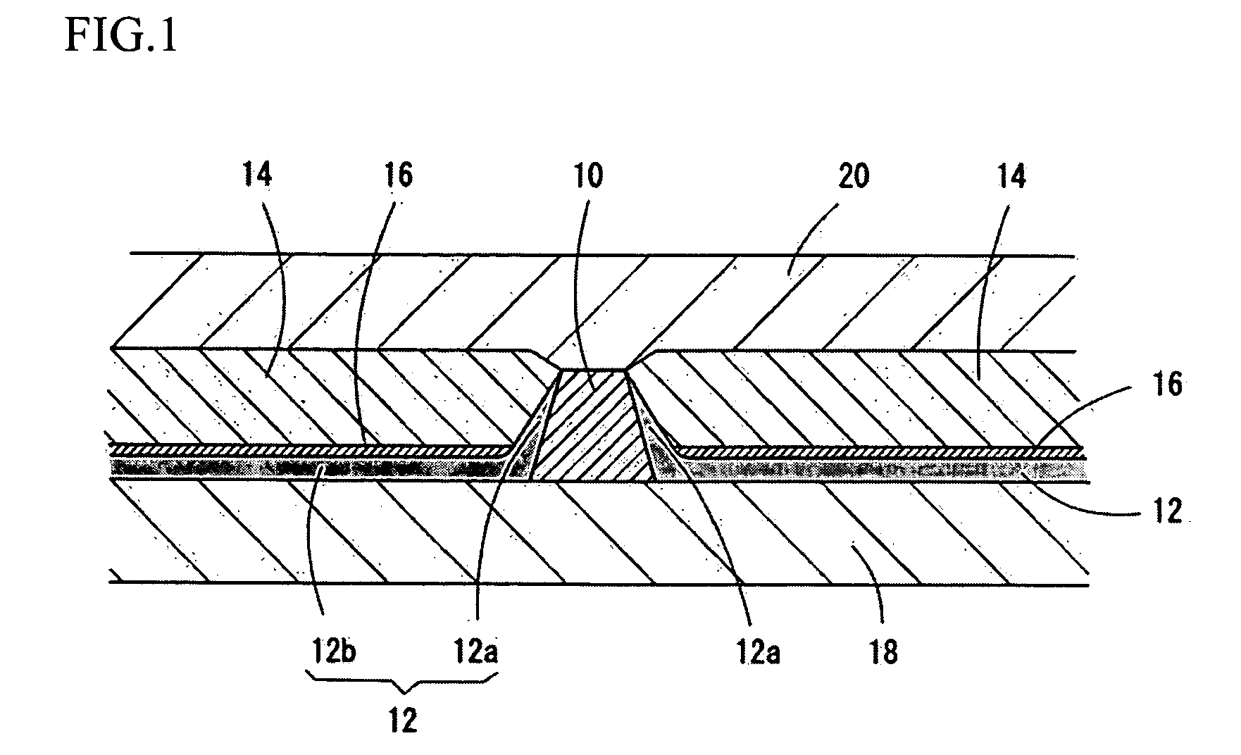
[0014]In the magnetic head, the base layer may be made of a material, which crystal-grows the hard magnetic layer so as to orient a magnetizing direction of the hard magnetic layer parallel to a surface of the base layer. With this structure, the hard magnetic layer is capable of effectively applying a bias magnetic field to the read-element.
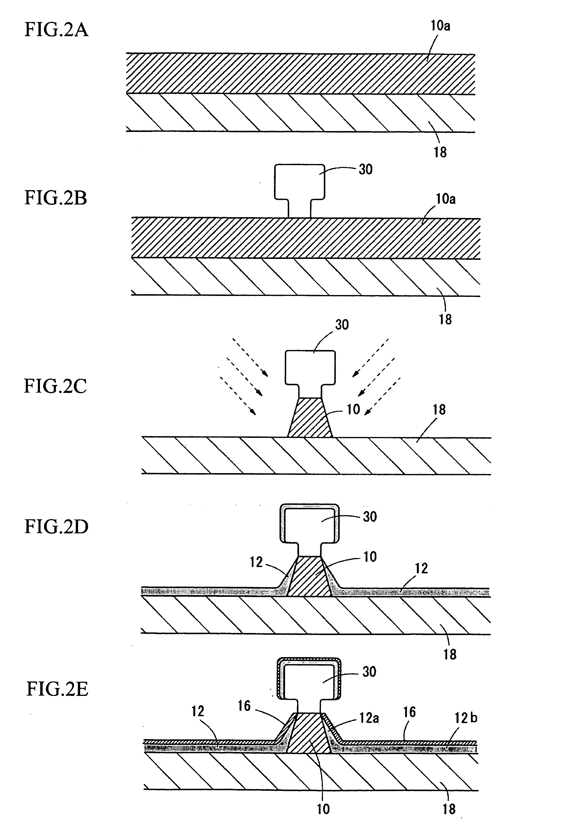
[0016]In the method, the hard magnetic layers may be formed by diagonally sputtering with respect to a surface of a work piece so as not form a gap between the side face of the read-element and the hard magnetic layers. Further, in the method, a material, which crystal-grows the hard magnetic layer so as to orient a magnetizing direction of the hard magnetic layers parallel to a surface of the base layer, may be used for forming the base layer on the insulating layer. In this case, the hard magnetic layer is capable of effectively applying a bias magnetic field to the read-element.
[0017]By employing the magnetic head and the method of the present invention, the hard magnetic layer can be located closer to the read-element, so that the bias magnetic field of the hard magnetic layer can be effectively applied to the read-element. Therefore, magnetic data detection performance of the read-head can be improved, and the magnetic head, which has stable characteristics, can be produced.

Problems solved by technology

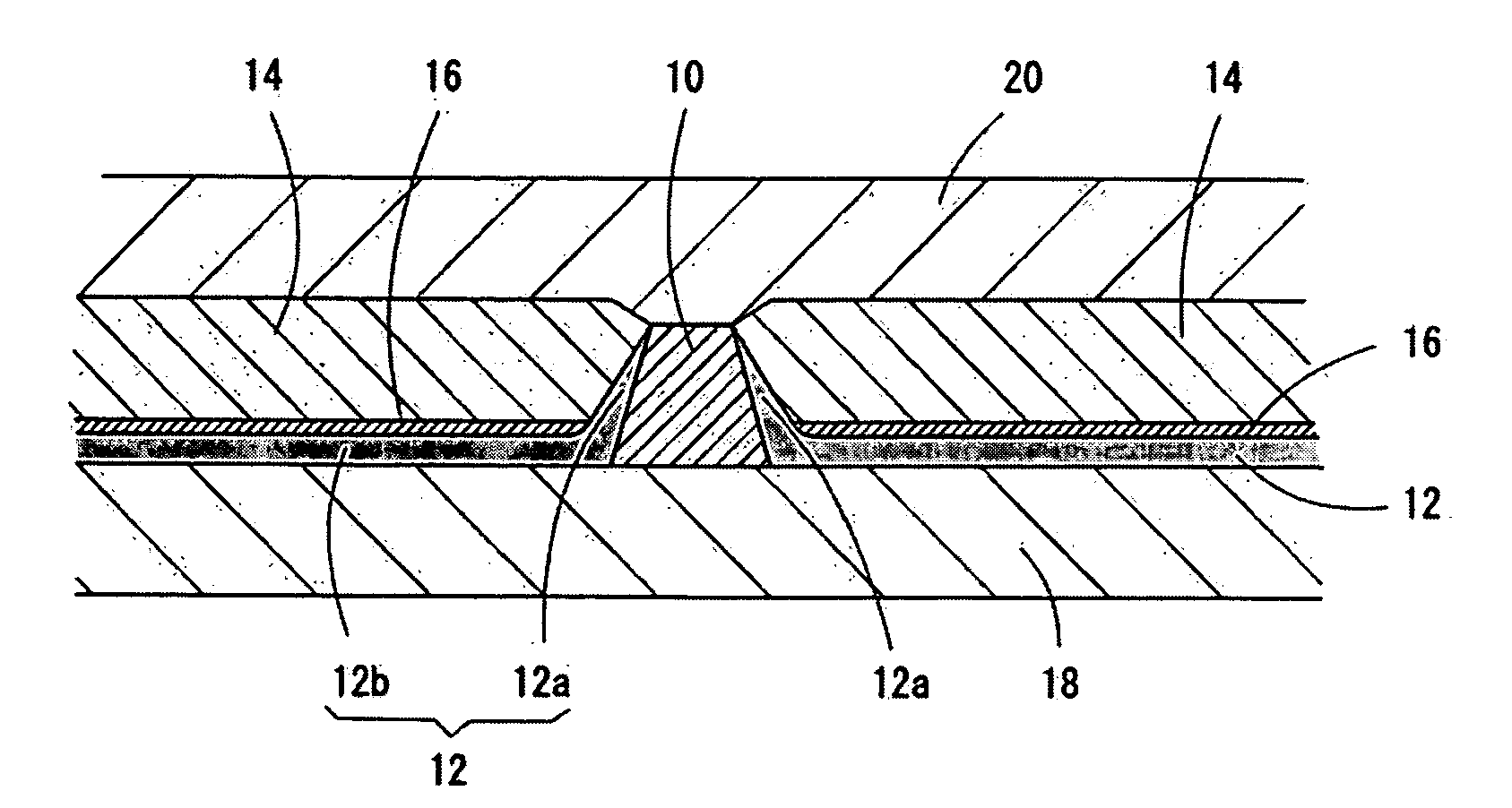
If the bias magnetic fields of the hard magnetic layers 14 are not suitably applied to the read-element 10, detection performance of the read-head will be worse.
However, ferromagnetic materials used for forming the hard magnetic layers 14 are limited; and if the insulating layers 12 are too thin, their electric insulation performance will be lost, so thinning the insulating layers 12 is also limited.

Method used


Image

  • Magnetic head and method of producing the same
  • Magnetic head and method of producing the same
  • Magnetic head and method of producing the same

Examples


Embodiment Construction

[0025]Preferred embodiments of the present invention will now be described in detail with reference to the accompanying drawings.

(Structure of The Magnetic Head)

[0026]FIG. 1 is a sectional view of a read-head of a magnetic head of the present embodiment seen from an air bearing surface side. The basic structure of the read-head is the same as that of the conventional read-head shown in FIG. 6. Namely, a lower shielding layer 8 and an upper shielding layer 20 sandwich the read-element 10 in the thickness direction. Side faces of the read-element 10 and parts of the lower shielding layer 18, which outwardly extend from the read-element 10, are respectively coated with insulating layers 12. Hard magnetic layers 14 are respectively provided on the both sides of the read-element 10. The hard magnetic layers 14 apply bias magnetic fields to a free layer of the read-element 10 so as to make the free layer have a single domain structure.

[0027]The read-head of the present embodiment is chara...


PUM


Abstract

The magnetic head is capable of effectively applying a bias magnetic field of a hard magnetic layer to the read-head so as to improve and stabilize detection performance. The magnetic head of the present invention comprises: a lower shielding layer; a read-element being formed on the lower shielding layer; an insulating layer continuously coating side faces of the read-element a surface of the lower shielding layer; a base layer being formed on the insulating layer; and a hard magnetic layer being formed on the base layer. Parts of the insulating layer, which coat the side faces of the read-element, are coated with no base layer.

Description

BACKGROUND OF THE INVENTION[0001]The present invention relates to a magnetic head and a method of producing the magnetic head, more precisely relates to a magnetic head, which includes a CPP (current perpendicular to the plane) type read-head and is characterized by arrangement of a hard magnetic layer, and a method of producing the magnetic head.[0002]FIG. 6 is a sectional view of a conventional magnetic head, which includes a CPP type read-head, seen from an air bearing surface side. In the CPP type read-head, a sensing current runs in a thickness direction (a film layering direction) of the read-element 10 so as to read magnetic data. Therefore, side faces of the read-element 10 and a surface of a lower shielding layer 18, on which the read-element 10 is formed, are coated with insulating layers 12, e.g., alumina.[0003]Hard magnetic layers 14 are formed on the both sides of the read-element 10. The hard magnetic layers 14 apply magnetic fields to a free layer of the read-element ...

Claims


Application Information

Patent Timeline
IPC IPC(8): G11B5/33
CPCB82Y25/00G01R33/093G11B5/3163H01L43/12G11B5/3932G11B5/398G11B5/3912H10N50/01H01R31/06
Inventor AKIE, MASANORI
Owner FUJITSU LTD
Learn More