
System for extracting hydrogen from a gas containing methane

a technology of methane and gas, applied in the direction of hydrogen separation using solid contact, sustainable manufacturing/processing, separation processes, etc., can solve the problems of comparatively small effort and expense required to achieve the carbon dioxide reduction described, and achieve the effect of simple and inexpensive methods

Inactive Publication Date: 2010-04-22
THYSSENKRUPP IND SOLUTIONS AG
View PDF8 Cites 7 Cited by
  • Summary
  • Abstract
  • Description
  • Claims
  • Application Information

AI Technical Summary

Benefits of technology

[0007]The invention is based on the task of indicating a simple and inexpensive method for extracting hydrogen from a gas that contains methane, particularly natural gas, in which only small amounts of carbon dioxide are given off into the environment.
[0010]Preferably, a conversion reactor that is operated at medium temperature, or a high-temperature conversion reactor with a subsequent low-temperature conversion reactor are used for the conversion stage. In this way, almost complete conversion of the carbon monoxide that has been formed to carbon dioxide is guaranteed, where the latter can subsequently be removed from the gas stream by way of the gas scrubber. When using a subsequent low-temperature conversion reactor, there is the advantage that the high-temperature conversion reactor of an existing hydrogen plant can continue to be used, thereby clearly lowering the retrofit costs for an existing plant.
[0012]If an existing H2 plant is retrofitted for the purpose of minimizing CO2, it is practical to compress the converted gas stream before it enters into the newly built CO2 scrubber, in order to equalize the pressure loss that results from this. In this way, the effectiveness of the CO2 scrubber is increased.

Problems solved by technology

The effort and expense required to achieve the carbon dioxide reduction described are comparatively slight.

Method used


Image

  • System for extracting hydrogen from a gas containing methane
  • System for extracting hydrogen from a gas containing methane
  • System for extracting hydrogen from a gas containing methane

Examples


Embodiment Construction

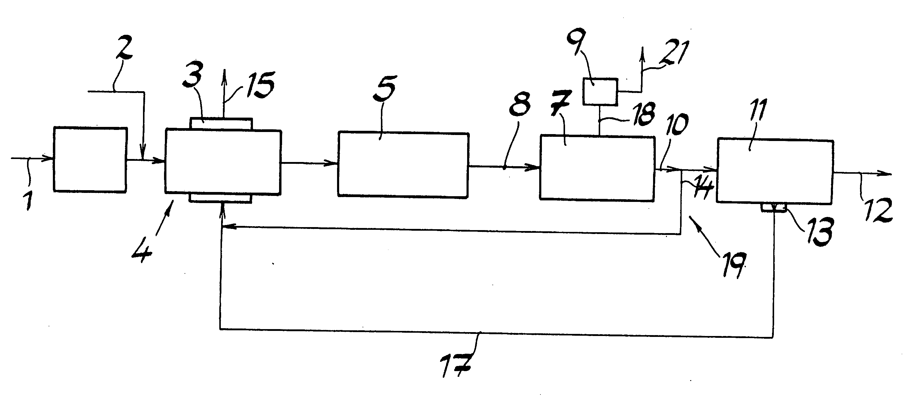
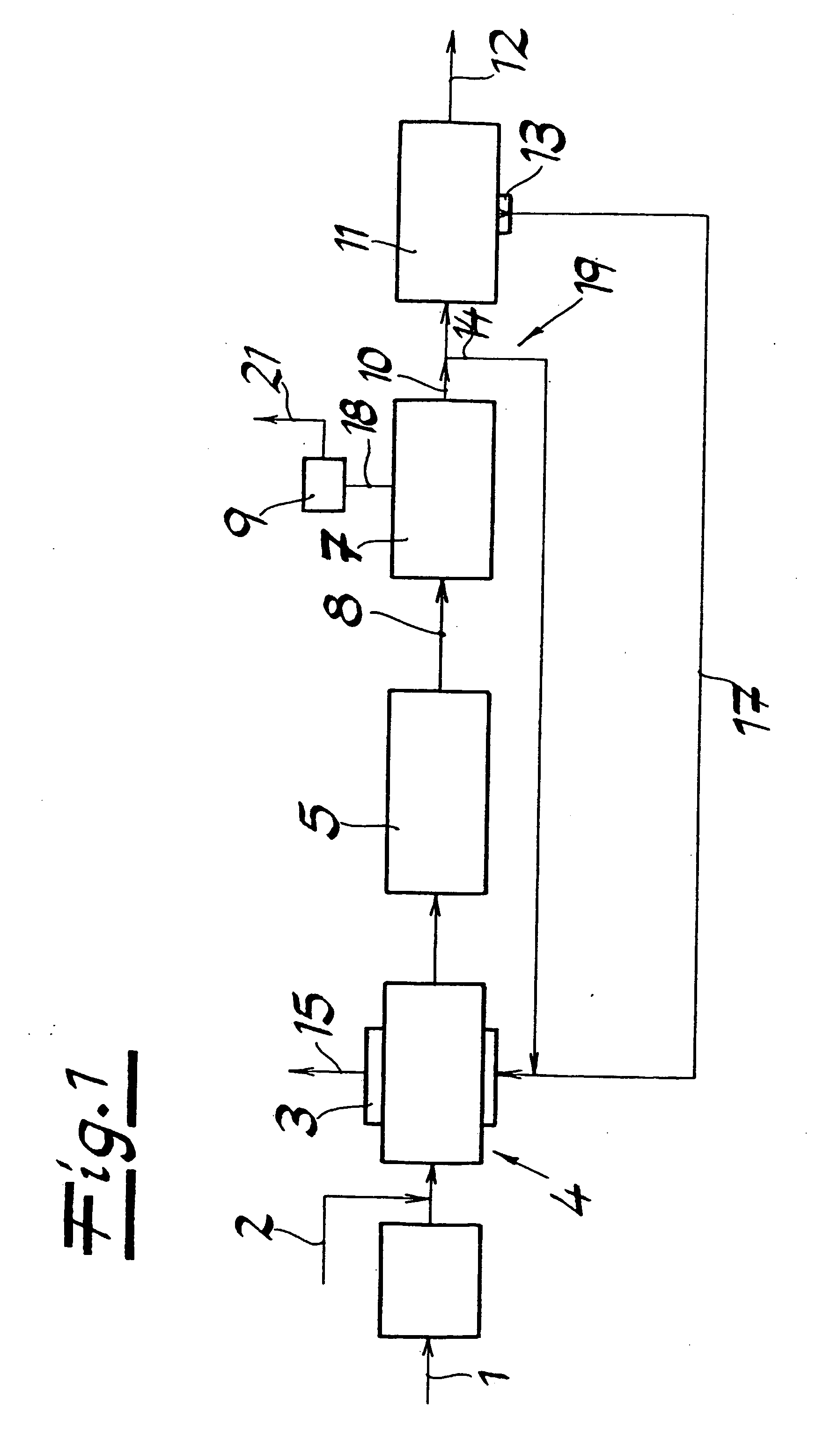
[0018]FIG. 1 shows a method according to the invention for extracting hydrogen from a natural gas that contains methane. A steam stream 2 is mixed into a natural gas stream 1. The hydrocarbons contained in the natural gas, particularly methane, are catalytically split into hydrogen, carbon monoxide, and carbon dioxide, in a reformer 4 equipped with a combustion chamber 3, using the steam stream 2 that is mixed in. This reformation takes place almost completely, so that practically no gases that contain hydrocarbons are present, any longer, at the exit from the reformer 4. In a subsequent conversion reactor 5 that is operated at medium temperature, catalytic conversion of the carbon monoxide that has formed to carbon dioxide and hydrogen takes place, using steam. This reaction also proceeds almost completely, so that the carbon monoxide content of the gas stream 8 that exits from the conversion reactor 5 is less than 1 vol.-% (dry). Subsequently, the carbon dioxide that has formed is...


PUM

PropertyMeasurementUnit
temperaturesaaaaaaaaaa

Abstract

A system for extracting hydrogen from a gas containing methane, especially natural gas. Hydrocarbons contained in the gas are catalytically broken down in a reformer by steam in order to form hydrogen, carbon monoxide and carbon dioxide. Catalytic conversion of the obtained carbon monoxide with steam occurs in a downstream conversion step in order to form carbon monoxide and water. Carbon dioxide is removed from the converted gas flow by gas washing, and the washed hydrogen-rich gas flow is subsequently divided in a pressure-swing adsorption system into a product gas flow made of hydrogen and a waste gas flow. The waste gas flow is introduced with hydrogen, which is separated from the gas flow after gas washing, into a reformer which is essentially a carbon-free combustible gas, and is combusted there.

Description

CROSS-REFERENCE TO RELATED APPLICATIONS[0001]This application is a divisional of and Applicants claim priority under 35 U.S.C. §§120 and 121 of parent U.S. patent application Ser. No. 10 / 566,268 filed Mar. 10, 2006. Applicants claim priority under 35 U.S.C. §119 of German Application No. 103 34590.6 filed Jul. 28, 2003. Applicants also claim priority under 35 U.S.C. §365 of PCT / EP2004 / 008322 filed Jul. 24, 2004. The international application under PCT article 21(2) was not published in English.BACKGROUND OF THE INVENTION[0002]1. Field of the Invention[0003]The invention relates to a method for extracting hydrogen from a gas that contains methane, particularly natural gas.[0004]2. The Prior Art[0005]A conventional hydrogen plant is known from U.S. Pat. No. 5,131,930, which is operated with natural gas as the starting material. In the plant, catalytic splitting, generally operated with steam, of hydrocarbons contained in the natural gas first takes place, in a heated reformer, to prod...

Claims


Application Information

Patent Timeline
Patent Type & Authority Applications(United States)
IPC IPC(8): B01J8/00B01D53/047C01B3/38C01B3/48C01B3/56C01B32/50C10J1/207
CPCB01D53/04Y02E60/324B01D2256/16B01D2257/7022C01B3/384C01B3/48C01B3/56C01B2203/00C01B2203/0233C01B2203/0283C01B2203/0288C01B2203/0415C01B2203/043C01B2203/0475C01B2203/0811C01B2203/0822C01B2203/0827C01B2203/1241C01B2203/143C01B2203/146Y02C10/08Y02C20/20Y02E60/364B01D53/047Y02E60/36Y02P20/10Y02C20/40Y02E60/32Y02P20/151
Inventor BLUMENFELD, MICHAELLIU, VINCENTMIELKE, BERNDMICHEL, MARCUS
Owner THYSSENKRUPP IND SOLUTIONS AG
Learn More