Current controlled biasing for current-steering based RF variable gain amplifiers

a current-steering-based variable gain amplifier and biasing technology, which is applied in the direction of antennas, modulation, transmission, etc., can solve the problems of inability to exhibit substantially linear voltage-current characteristics of cmos transistors in general, relatively new manufacturing technologies, and high cost of manufacturing these rf devices

Active Publication Date: 2010-04-15
ICERA CANADA ULC
View PDF31 Cites 10 Cited by
  • Summary
  • Abstract
  • Description
  • Claims
  • Application Information

AI Technical Summary

Benefits of technology

[0024]In a further aspect of the present embodiment, the variable gain amplifier includes an input stage, a mirror transistor and a diode-connected transistor. The input stage couples a current to a differential amplification stage in response to the data signal, and the differential amplification stage provides an amplified signal corresponding to the data signal in response to the differential gain control voltages. The mirror transistor provides the current to the input stage, and the diode-connected transistor receives the variable current, where the diode-connected transistor is arranged in a current mirror configuration with the mirror transistor. Furthermore, the bias current source includes a hybrid current source for providing a combination of proportional to absolute temperature (PTAT) current and complementary to absolute temperature (CTAT) current. The hybrid current source can include an adjustable PTAT current source for providing the PTAT current, an adjustable CTAT current source for providing the CTAT current, a current summer for combining the PTAT current and the CTAT current, and a mirror transistor. The current mirror transistor being arranged in a current mirror configuration with the current summer for providing the bias current, where the bias current has a magnitude corresponding to the sum of the PTAT current and the CTAT current.
[0025]According to yet another aspect of the present embodiment, the adjustable PTAT current source includes at least two PTAT current sources for providing different PTAT currents and a PTAT switch circuit for selectively coupling at least one of the at least two PTAT current sources to a common node for providing the PTAT current. The adjustable CTAT current source includes at least two CTAT current sources for providing different CTAT currents, and a CTAT switch circuit for selectively coupling at least one of the at least two CTAT current sources to another common node for providing the CTAT current. The adjustable PTAT current source is programmed to provide a first ratio factor of the bias current and the adjustable CTAT current source is programmed to provide a second ratio factor of the bias current, where the first ratio factor and the second ratio factor sum to approximately 1. The adjustable PTAT current source is programmed in response to a first ratio control word and the adjustable CTAT current source is programmed in response to a second ratio control word.
[0026]In yet a further aspect of the present embodiment, the first ratio control word and the second ratio control word are adjusted in response to a sensed temperature. The gain system further includes a temperature sensor and a temperature decoder. The temperature sensor providing an analog signal corresponding to the sensed temperature. The temperature decoder generating the first ratio control word and the second ratio control word in response to the analog signal received from the temperature sensor. The temperature decoder includes an analog to digital converter, a first decoder, and a second decoder. The analog to digital converter provides a digital output signal corresponding to the analog signal. The first decoder receives the digital output signal and generates the first ratio control signal. The second decoder receives the digital output signal and generates the second ratio control signal.
[0027]In a second aspect, the present invention provides a gain system for a wireless transmitter core. The gain system including a variable gain amplifier, a temperature sensor, a temperature decoder, and a current controller. The variable gain amplifier receives a variable current for amplifying a data signal with the level of gain in response to different

Problems solved by technology

However, such manufacturing technologies are relatively new, very complex, and hence expensive.
Consequently, the costs for manufacturing these RF devices can be prohibitive.
In fact, CMOS transistors in general do not exhibit substantially linear voltage-current characteristics.
Therefore, any wireless core employing such an AGC circuit will not meet the WCDMA standard.
This is mainly due to the inherent non-linear behaviour of CMOS transistors operating in a saturation mode.
Hence voltage headroom is reduced, which can lead to clipping of the input signal.
In addition to noise, the numerous voltage to current and current to voltage conversion stages will consume current and therefore waste power, which is a limited resource in mobile wireless devices.
While the inherent non-linearity of CMOS variable gain circuits can be compensated / corrected with existing circuits, they are limited to a 40 dB range that is insufficient for WCDMA standards.
Furthermore, the noise added by the mixer circuit and the variable gain circuit necessitates an off-chip SAW filter discrete component, potentially increasing the wireless device form factor and cost due to the additional device.

Method used


Image

  • Current controlled biasing for current-steering based RF variable gain amplifiers
  • Current controlled biasing for current-steering based RF variable gain amplifiers
  • Current controlled biasing for current-steering based RF variable gain amplifiers

Examples


Embodiment Construction

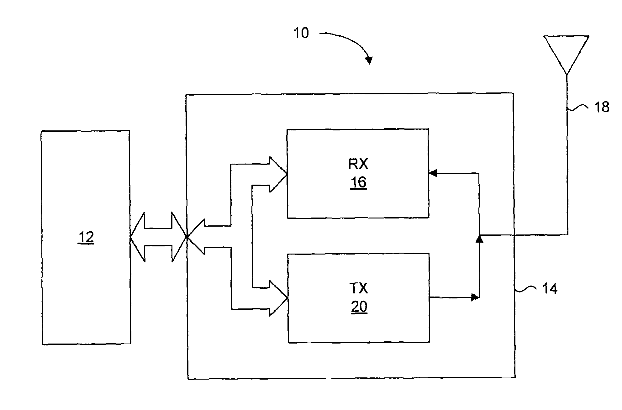
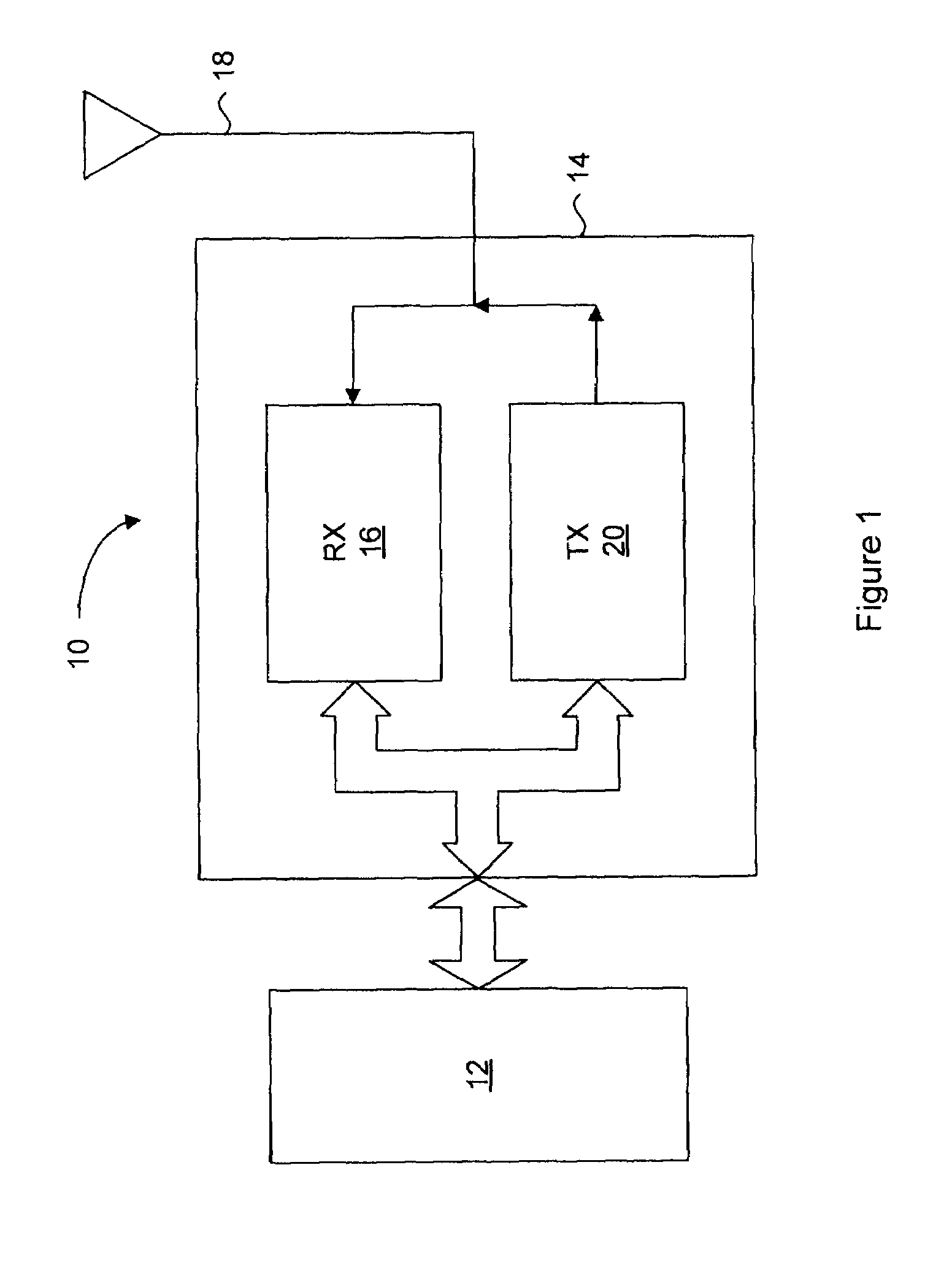
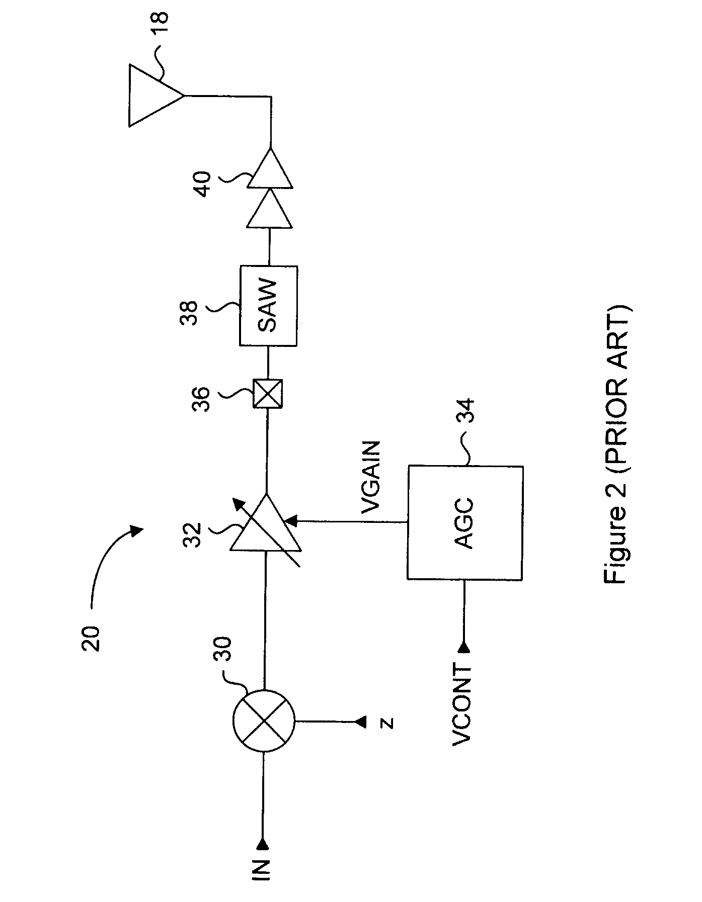
[0057]Generally, the present invention provides a CMOS automatic gain control (AGC) circuit that receives an analog control voltage and generates a temperature compensated gain voltage to linearly control the gain of a variable gain circuit operating in the sub-threshold region. A PTAT circuit having a resistor network coupled to a current mirror circuit operating in the sub-threshold region establishes a current having an proportional relationship to temperature. This current is used as a supply for a voltage to voltage converter circuit, which generates an intermediate voltage in response to the analog control voltage. A linearizing circuit operating in the sub-threshold region pre-conditions the intermediate voltage, which is then applied to a variable gain circuit. The variable gain circuit is operated in the sub-threshold region, and the preconditioned intermediate voltage will control the amount of gain to be substantially linear with respect to the analog control voltage, and...


PUM


Abstract

An adaptive current control circuit for reduced power consumption and minimized gain shift in a variable gain amplifier. An automatic gain control circuit provides gain control voltages in response to a gain control signal. The gain control voltages are used by the variable gain amplifier to set the gain of the output signal for wireless transmit operations. The adaptive current control circuit receives the same gain control voltages for reducing current to the variable gain amplifier during low gain operation, while providing higher currents during high gain operation. The current that is provided is a hybrid mix of proportional to absolute temperature (PTAT) current and complementary to absolute temperature (CTAT) current for minimizing temperature effects on the gain. The ratio of PTAT current and CTAT current is adjustable for specific temperature ranges to further minimize temperature effects on the gain.

Description

CROSS REFERENCE TO RELATED APPLICATIONS[0001]This application is a Continuation-In-Part of U.S. patent application Ser. No. 11 / 409,092, and claims priority to U.S. Provisional Application No. 60 / 871,323, filed on Dec. 21, 2006.FIELD OF THE INVENTION[0002]The present invention relates generally to wireless communication systems. More particularly, the present invention relates to automatic gain control in wireless communication systems.BACKGROUND OF THE INVENTION[0003]Wireless devices have been in use for many years for enabling mobile communication of voice and data. Such devices can include mobile phones and wireless enabled personal digital assistants (PDA's) for example. FIG. 1 is a generic block diagram of the core components of such wireless devices. The wireless core 10 includes a baseband processor 12 for controlling application specific functions of the wireless device and for providing and receiving voice or data signals to a radio frequency (RF) transceiver chip 14. The RF...

Claims


Application Information

Patent Timeline
IPC IPC(8): H04B1/04
CPCH03G3/3042H03G1/04
Inventor EMBABI, SHERIF H.K.BELLAOUAR, ABDELLATIFFRECHETTE, MICHEL J.G.J.P.
Owner ICERA CANADA ULC
Why Eureka
Try Eureka