
Information processing device

a technology of information processing and processor core, which is applied in the direction of digital computer details, instruments, generating/distributing signals, etc., can solve the problems of power consumption increase, power scaling as used to be inability to be desired, and the ratio of performance per power dissipation is largely decreased, so as to reduce the processing performance of each processor core, suppress the power consumption of the processor core, and achieve high-speed operation of the bus

Inactive Publication Date: 2010-04-01
HITACHI LTD
View PDF4 Cites 16 Cited by
  • Summary
  • Abstract
  • Description
  • Claims
  • Application Information

AI Technical Summary

Benefits of technology

The present invention provides an information processing device with high processing performance and high ratio of performance per power dissipation. This is achieved by operating multiple processor cores in parallel, while compensating for a decrease in processing performance in each core by high speed operation of the bus and supplying a power supply voltage higher than the power supply voltage supplied to the processor cores. This results in a decrease of power consumption and an improvement of the ratio of performance per power dissipation. The invention also includes a configuration for individually reducing power consumption by reducing the supplied voltage to each circuit block.

Problems solved by technology

However, recently, even if the power supply voltage is decreased by micro-fabrication of a process, an increase of leakage current overcomes a decrease of switching current, and therefore, such a power scaling as used to be cannot be desired.
However, in this method, when the processor cores are operated at high frequency (for example, a few GHz) for improving absolute performance, the power supply voltage must be set to high, and therefore, the power consumption increases, and as a result, a ratio of performance per power dissipation is largely decreased.
More particularly, power dissipation of 200 W or more is consumed in the operation of 5.67 GHz, and therefore, cooling of the SoC becomes a large issue.
However, Patent Document 1 neither describes nor suggests a configuration for improving the ratio of performance per power dissipation as reducing the power consumption.

Method used


Image

  • Information processing device
  • Information processing device
  • Information processing device

Examples


first embodiment

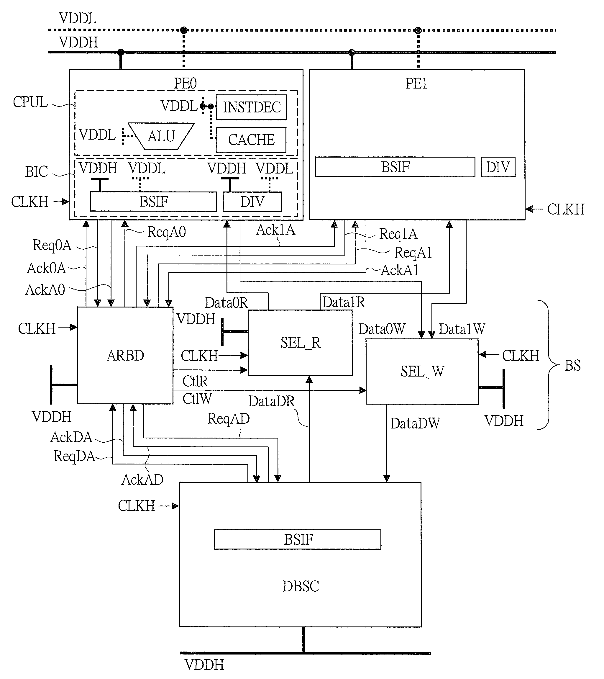
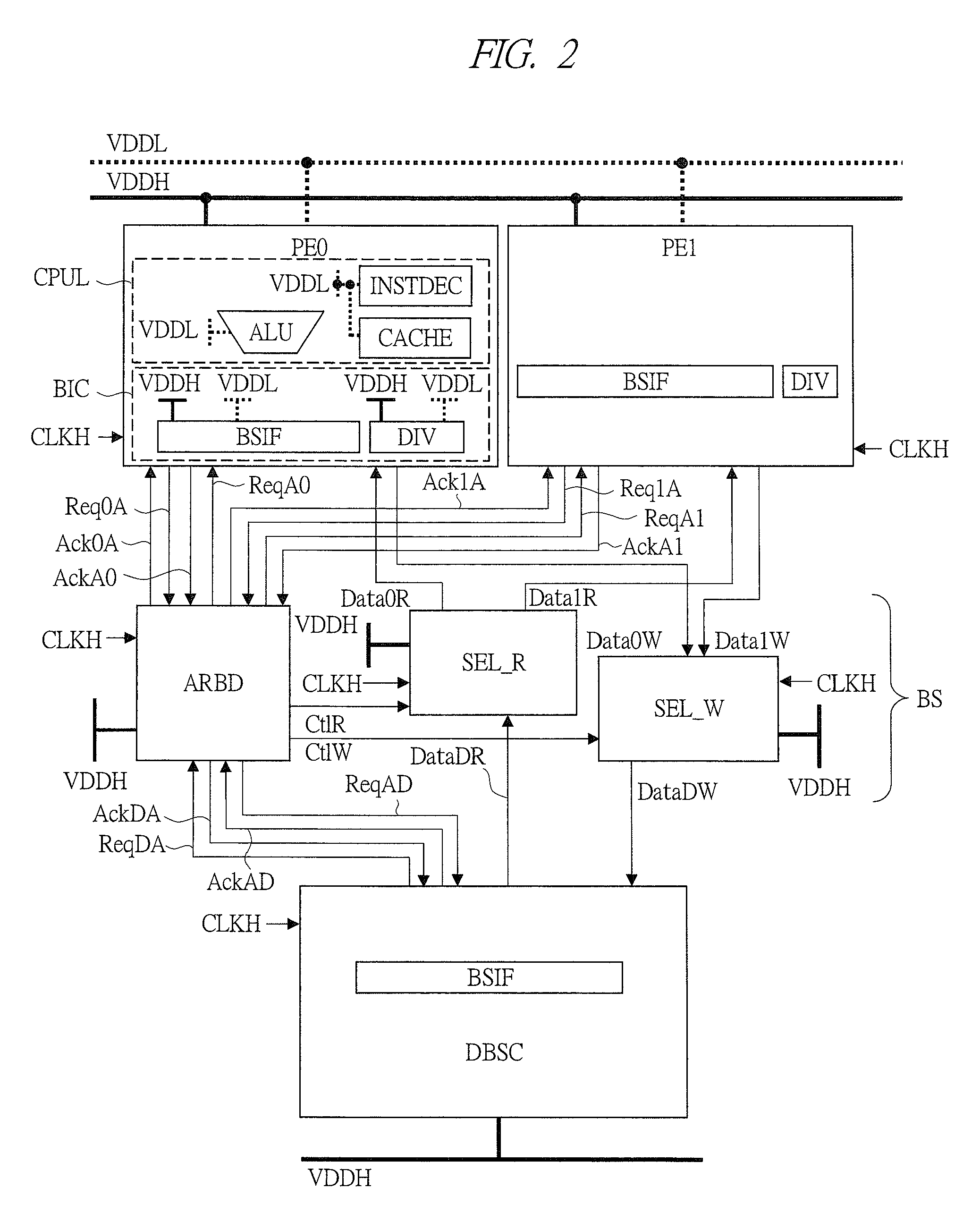
[0039]In an information processing device according to the present embodiment, for realizing high ratio of performance per power dissipation as well as high performance, such a method is used that, a low power supply voltage is applied to many general-purpose processor cores and dedicated processor cores to be operated at low frequency, and a high power supply voltage is applied to a global clock, a bus, a memory, and an oscillating circuit such as a PLL (hereinafter, these four elements are collectively called “global system”) to be operated at high frequency. By using this method, the ratio of performance per power dissipation per one processor core can be improved as the square of the power supply voltage by decreasing the power supply voltage of the processor core. Although the processing performance decreases linearly with the decrease of the frequency, the absolute performance can be ensured by operating many processor cores in parallel with regard to this. Further, in data co...

second embodiment

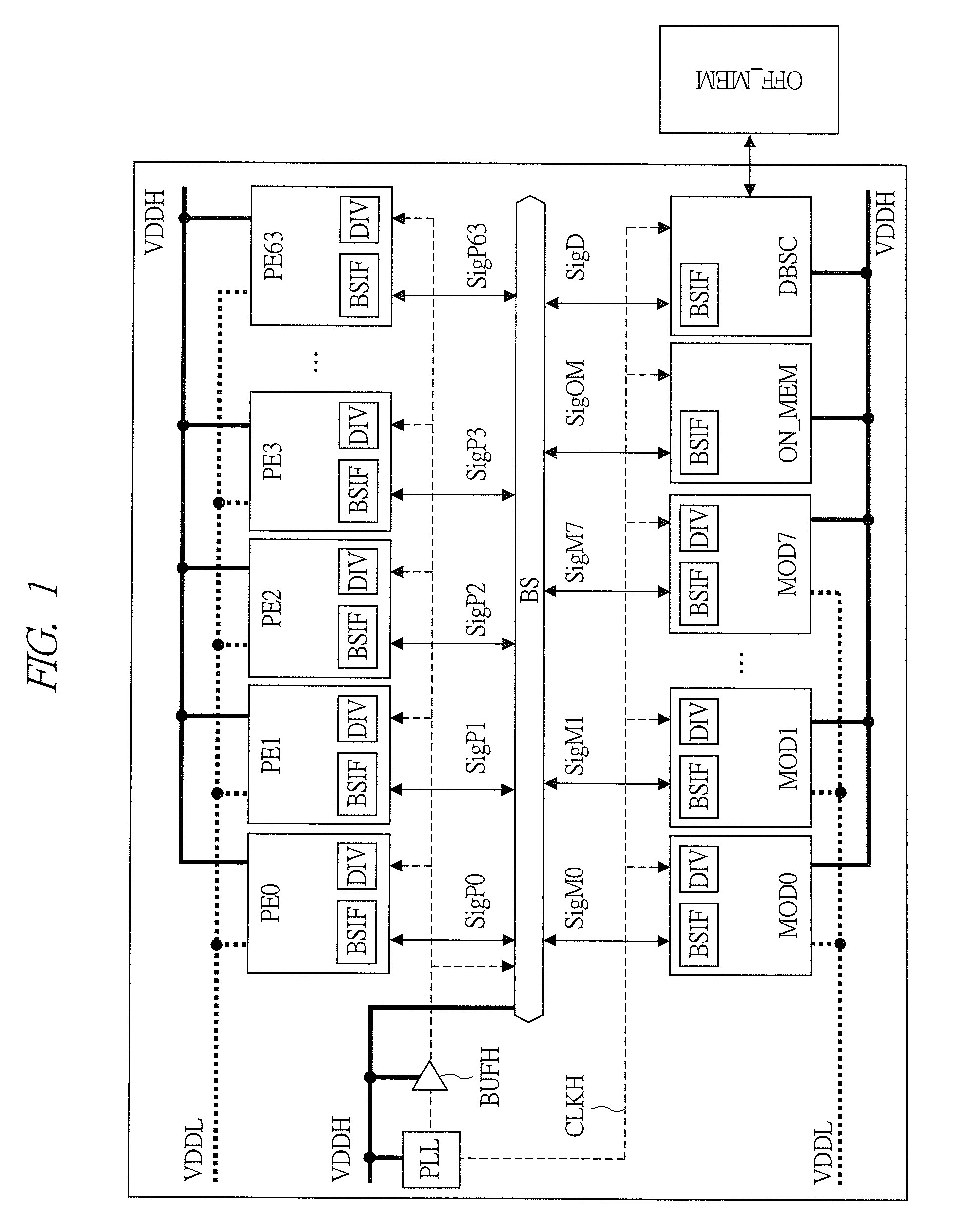
[0092]FIG. 17 is a block diagram showing one example of a configuration in an information processing device according to a second embodiment of the present invention. In the configuration example shown in FIG. 17, an oscillator PLLH of the clock with high amplitude and high frequency CLKH and an oscillator PLLL of the clock with low amplitude and low frequency CLKL are individually mounted instead of the oscillator PLL shown in FIG. 1 compared with the configuration example in FIG. 1. The high voltage VDDH is supplied to PLLH, and the low voltage VDDL is supplied to PLLL. PLLH and PLLL are controlled by a clock control signal ClkEn transmitted from a clock controller CKCTL. CLKH is propagated by a buffer circuit BUFH for a clock with high amplitude and high frequency, and CLKL is propagated by a buffer circuit BUFL for a clock with low amplitude and low frequency. Note that, although each of BUFH and BUFL are shown to be represented by only one piece, any number of pieces of BUFH ma...

third embodiment

[0097]FIG. 20 is a block diagram showing one example of a configuration of an information processing device according to a third embodiment of the present invention. If there is a margin in the area of the SoC, it is possible to mount two on-chip-memory modules (ON_MEM0 and ON_MEM1) on the SoC. For description of a power supply wire connection inside of ON_MEM, an inside of only ON_MEM0 is described as a representative. As main constituent elements of ON_MEM0, although there are an interface section BIC2 including a bus interface BSIF and a frequency divider DIV, a memory section MEMB including an address controller ADRC and a memory cell array ARY, and the like, it may be configured with other elements except for these elements. Although there are two types of VDDH and VDDL as the power supply which is supplied to ON_MEM0, two types of VDDH and VDDL are supplied to the interface section BIC2 including BSIF and DIV which performs the frequency conversion and the level conversion, an...


PUM


Abstract

In a configuration provided with, for example, sixty four pieces of processor cores, an on-chip-memory, a bus commonly connected thereto, and others, the processor cores are operated by a power supply with low voltage and a clock with low frequency, and the bus is operated by a power supply with high voltage and a clock with high frequency. Each of the processor cores is provided with a bus interface and a frequency divider in order to absorb a power supply voltage difference and a frequency difference between the bus and each of them. The frequency divider generates the clock with low frequency from the clock with high frequency, and the bus interface is provided with a level shifting function, a data width converting function, a hand shaking function between the bus and the bus interface, and the like.

Description

CROSS-REFERENCE TO RELATED APPLICATION[0001]The present application claims priority from Japanese Patent Application No. 2008-251122 filed on Sep. 29, 2008, the content of which is hereby incorporated by reference into this application.TECHNICAL FIELD OF THE INVENTION[0002]The present invention relates to an information processing device, and more particularly, the present invention relates to a processing method for realizing high processing performance in a power saving manner by using a plurality of general-purpose processors or a plurality of dedicated processors.BACKGROUND OF THE INVENTION[0003]For example, as the method for realizing high processing performance by using the plurality of general-purpose processors or the plurality of dedicated processors, there is a technique for integrating many general-purpose processors having high processing performance. As such a technique, for example, a network chip mounting eighty pieces of processing engines (PE) is described in Non-Pa...

Claims


Application Information

Patent Timeline
Patent Type & Authority Applications(United States)
IPC IPC(8): G06F15/76G06F1/10G06F1/26G06F9/02
CPCG06F1/10Y02B60/1217G06F1/3203Y02D10/00
Inventor ONOUCHI, MASAFUMIMIZUNO, HIROYUKIKANNO, YUSUKESAEN, MAKOTO
Owner HITACHI LTD
Learn More