
Delegated virtualization in a multi-core processor (MCP)

a multi-core processor and delegated virtualization technology, applied in the field of delegated virtualization in a (, can solve the problems of low utilization of multi-core processors (mcps), symmetric mcps, and high power consumption of stand-by spes, and achieve continuous leakage, low utilization rate, and high utilization ra

Active Publication Date: 2010-04-01
KYNDRYL INC
View PDF47 Cites 4 Cited by
  • Summary
  • Abstract
  • Description
  • Claims
  • Application Information

AI Technical Summary

Benefits of technology

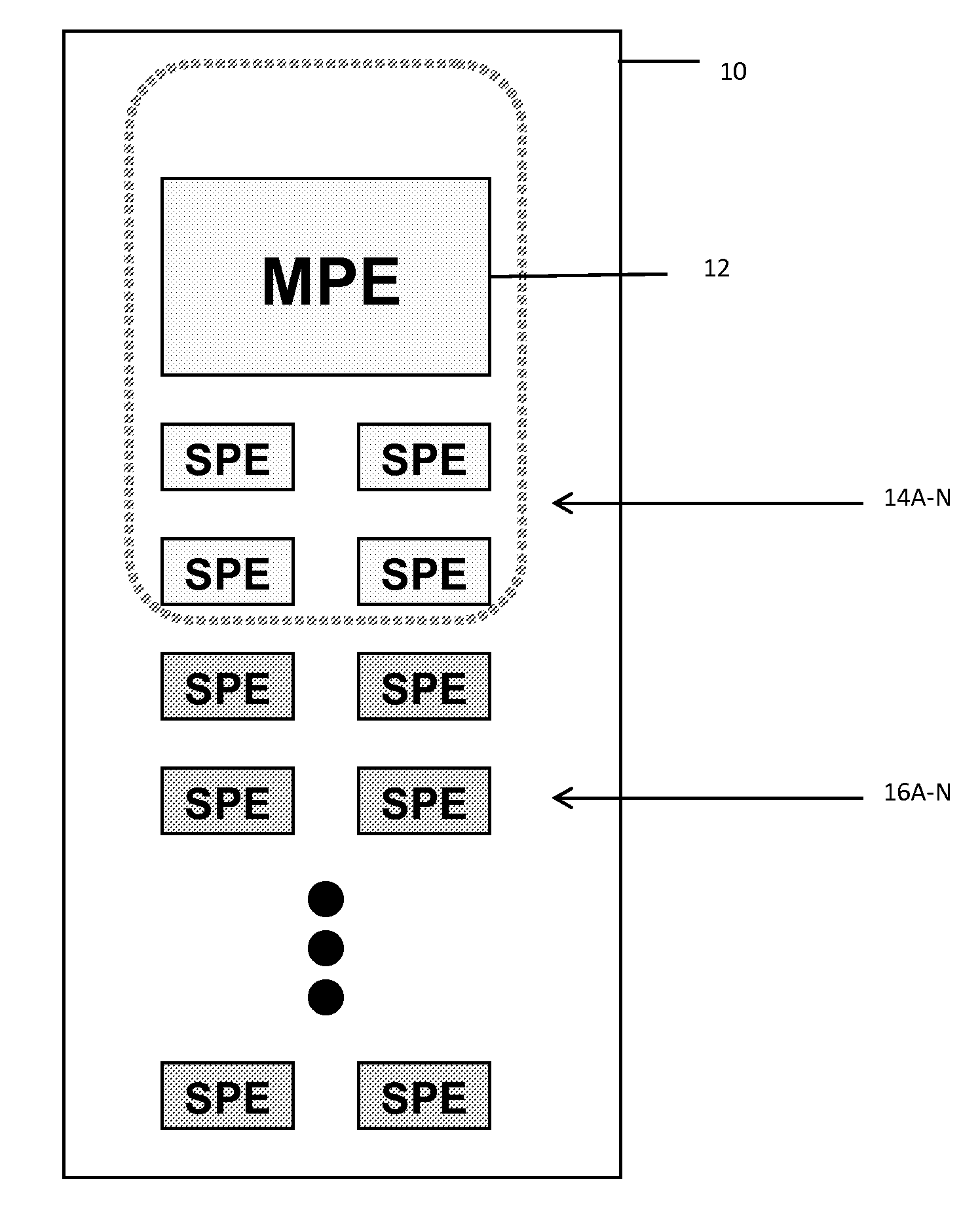
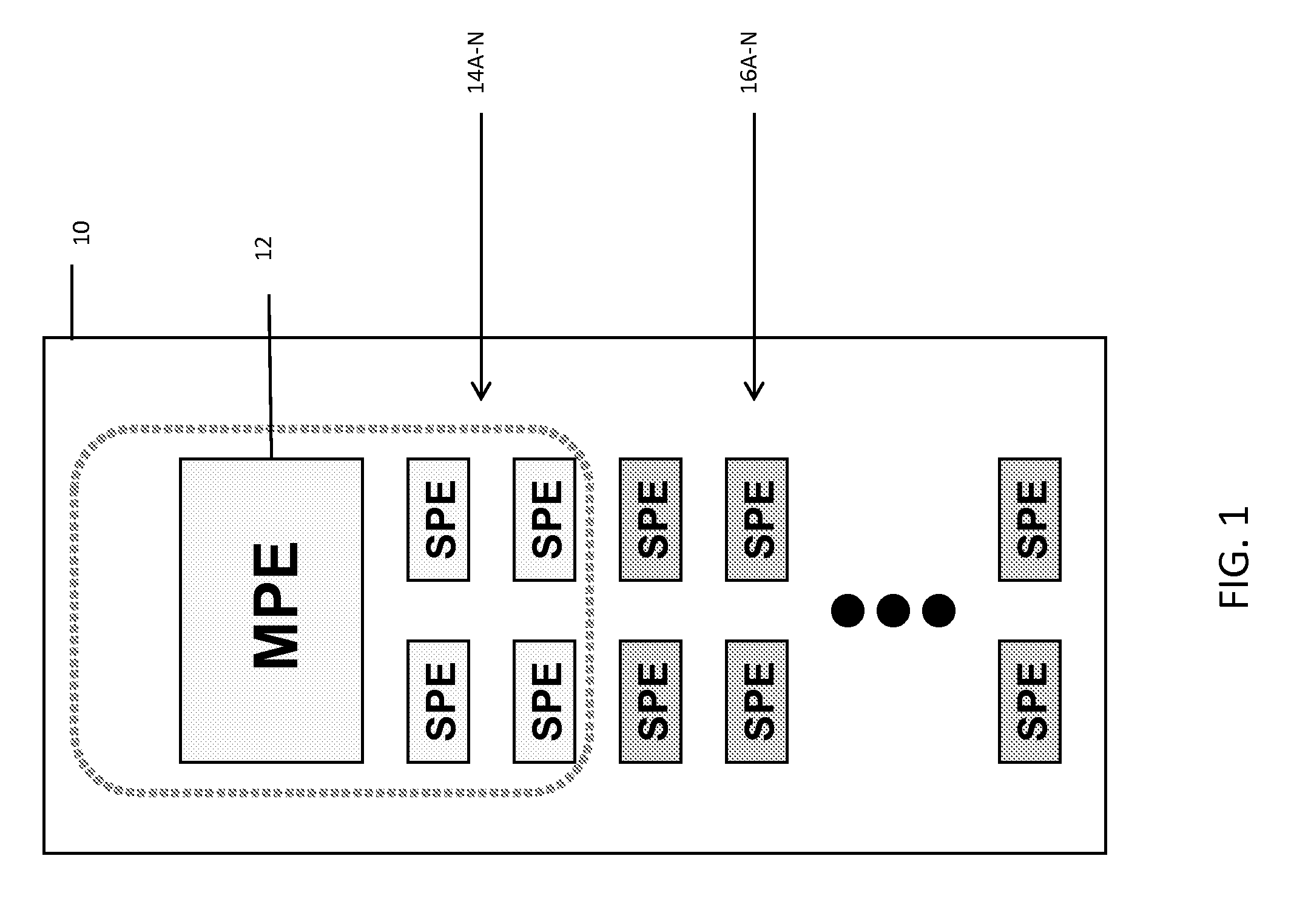
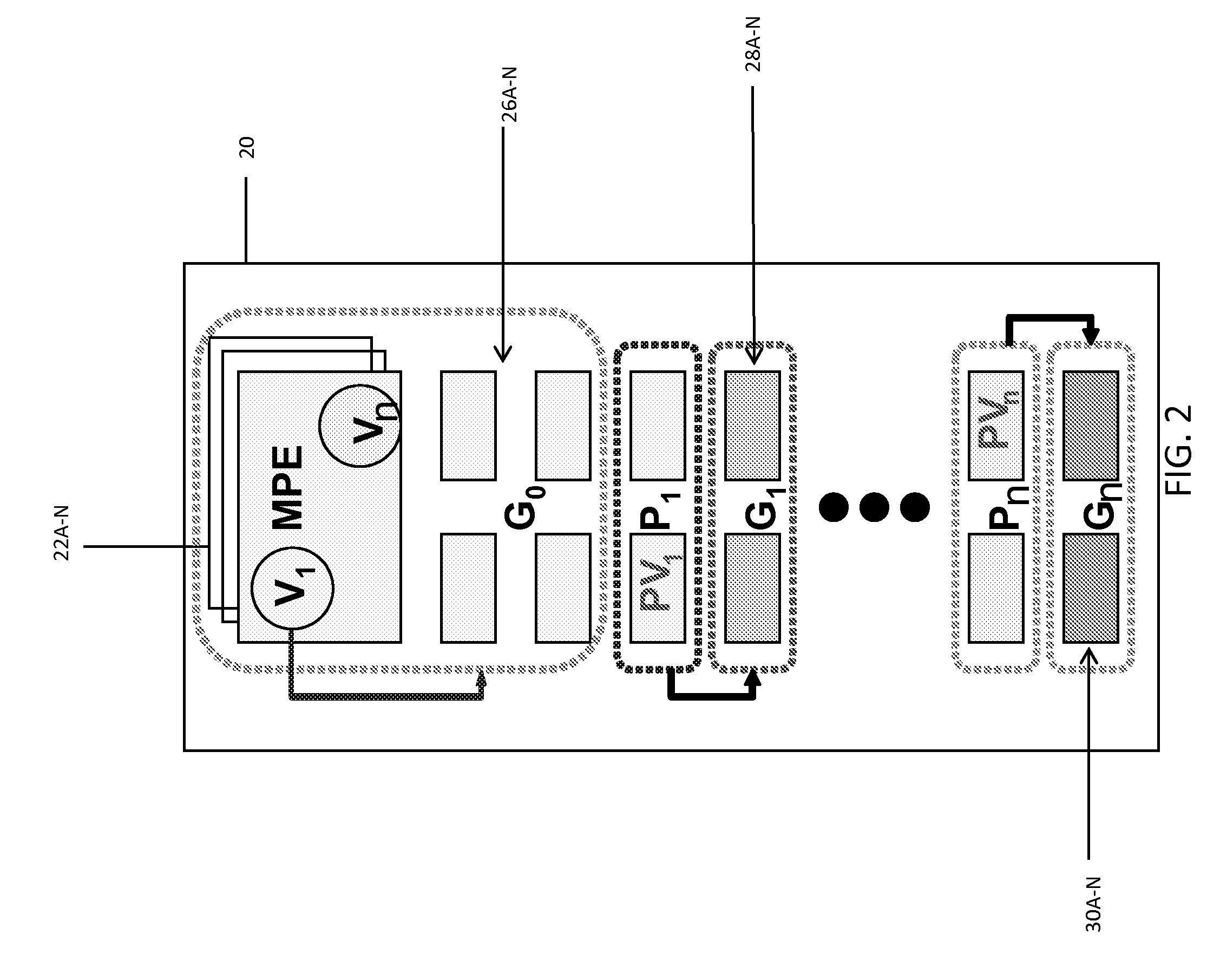
[0004]This disclosure describes an apparatus, computer architecture, method, operating system, compiler, and application program products for MPEs as well as delegated virtualization in a (e.g., symmetric) MCP. The disclosure is applied to a generic microprocessor architecture with a set (e.g., one or more) of controlling elements (e.g., MPEs) and a set of groups of sub-processing elements (e.g., SPEs). Under this arrangement, MPEs and SPEs are organized in a way that a smaller number MPEs control the behavior of a group of SPEs using program code embodied as a set of virtualized control threads. The arrangement also enables MPEs to delegate functionality to one or more groups of SPEs such that those group(s) of SPEs may act as pseudo MPEs. The pseudo MPEs may utilize pseudo virtualized control threads to control the behavior of other groups of SPEs. In a typical embodiment, the apparatus includes a MCP coupled to a power supply coupled with cores to provide a supply voltage to each core (or core group) and controlling-digital elements and multiple instances of sub-processing elements.
[0005]A first aspect of the present invention provides a multi-core processor, comprising: a main processing element comprising a set of virtualized control threads; a first group of sub-processing elements associated with main processing element via at least one set of virtualized control threads; and a group of sub-processing elements designated as a pseudo main processing element, the pseudo main element comprising a set of pseudo virtualized control threads.
[0006]A second aspect of the present invention provides a processing system comprising: a main processing element; a first group of sub-processing elements; a virtualized control thread associating the main processing element with the first group of sub-processing elements, the set of virtualized control threads controlling the first group of sub-processing elements; a pseudo main processing element; a second group of sub-processing elements; and a pseudo virtualized control thread associating the pseudo main processing element with the second group of sub-processing elements, the set of virtualized control threads controlling the group of sub-processing elements.
[0007]A third aspect of the present invention provides a processing method comprising: associating a main processing element with a first group of sub-processing element using a set of virtualized control threads; delegating a set of functions of the main processing element to a second group of sub-processing elements to cause the second group of sub-processing elements to act as a pseudo main processing element; associating the pseudo main processing element with a third group of sub-processing elements using a set of pseudo virtualized control threads; and controlling the first group of sub-processing elements using the set of virtualized control threads and the third group of sub-processing elements using the set of pseudo virtualized control threads.
[0008]A fourth aspect of the present invention provides a method for deploying a processing system comprising: providing a multi-core processor comprising: a main processing element comprising a set of virtualized control threads; a first group of sub-processing elements associated with main processing element via at least one of set of virtualized control threads; and a group of sub-processing elements designated as a pseudo main processing element, the pseudo main element comprising a set of pseudo virtualized control threads.
[0009]A fifth aspect of the present invention provides a computer-implemented business method comprising: associating a main processing element with a first group of sub-processing element using a set of virtualized control threads; delegating a set of functions of the main processing element to a second group of sub-processing elements to cause the second group of sub-processing elements to act as a pseudo main processing element; associating the pseudo main processing element with a third group of sub-processing elements using a set of pseudo virtualized control threads; and controlling the first group of sub-processing elements using the set of virtualized control threads and the third group of sub-processing elements using the set of pseudo virtualized control threads.

Problems solved by technology

Low utilization of Multi-Core Processors (MCPs) has been a major drawback of symmetric MCPs.
Also, design inflexibility forces continuous leakage current in the unloaded and stand-by sub-elements, such as Sub-Processing Element (SPE), so that the power is wasted.
Such stand-by SPEs consume high levels of power and continuously leak.
Typically, a MCP is used for the high performance digital processor scaling, but due to the complexity of the MCP design, the utilization and the efficiency of the software become challenging to optimize as the MCP dimension increases.

Method used


Image

  • Delegated virtualization in a multi-core processor (MCP)
  • Delegated virtualization in a multi-core processor (MCP)
  • Delegated virtualization in a multi-core processor (MCP)

Examples


Embodiment Construction

[0014]As indicated above, this disclosure describes an apparatus, computer architecture, method, operating system, compiler, and application program products for MPEs as well as delegated virtualization in a (e.g., symmetric) MCP. The disclosure is applied to a generic microprocessor architecture with a set (e.g., one or more) of controlling elements (e.g., MPEs) and a set of groups of sub-processing elements (e.g., SPEs). Under this arrangement, MPEs and SPEs are organized in a way that a smaller number MPEs control the behavior of a group of SPEs using program code embodied as a set of virtualized control threads. The arrangement also enables MPEs delegate functionality to one or more groups of SPEs such that those group(s) of SPEs will act as pseudo MPEs. The pseudo MPEs will utilize pseudo virtualized control threads to control the behavior of other groups of SPEs. In a typical embodiment, the apparatus includes a MCP coupled to a power supply coupled with cores to provide a sup...


PUM


Abstract

The disclosure is applied to a generic microprocessor architecture with a set (e.g., one or more) of controlling elements (e.g., MPEs) and a set of groups of sub-processing elements (e.g., SPEs). Under this arrangement, MPEs and SPEs are organized in a way that a smaller number MPEs control the behavior of a group of SPEs using program code embodied as a set of virtualized control threads. The arrangement also enables MPEs delegate functionality to one or more groups of SPEs such that those group(s) of SPEs will act as pseudo MPEs. The pseudo MPEs will utilize pseudo virtualized control threads to control the behavior of other groups of SPEs. In a typical embodiment, the apparatus includes a MCP coupled to a power supply coupled with cores to provide a supply voltage to each core (or core group) and controlling-digital elements and multiple instances of sub-processing elements.

Description

CROSS-REFERENCE TO RELATED APPLICATION[0001]The present invention is related in some aspects to co-pending an commonly owned application entitled Virtualization in a Multi-Core Processor (MCP) having attorney docket number END920080352US1, which was filed on Sep. 11, 2008, and assigned application Ser. No. 12 / 208,651, the entire contents of which are herein incorporated by reference.FIELD OF THE INVENTION[0002]The present invention generally relates to delegated virtualization in a (e.g., symmetric) multi-core processor (MCP). Specifically, the present invention delegates functions found in a main processing element to a group of sub-processing elements to yield a pseudo main processing element.BACKGROUND OF THE INVENTION[0003]Low utilization of Multi-Core Processors (MCPs) has been a major drawback of symmetric MCPs. Also, design inflexibility forces continuous leakage current in the unloaded and stand-by sub-elements, such as Sub-Processing Element (SPE), so that the power is wast...

Claims


Application Information

Patent Timeline
Patent Type & Authority Applications(United States)
IPC IPC(8): G06F15/76G06F9/06
CPCG06F9/5027G06F2209/509Y02B60/142Y02D10/00
Inventor DUVALSAINT, KARL J.HOFSTEE, HARM P.KIM, DAEIKKIM, MOON J.
Owner KYNDRYL INC
Learn More