Heater lamp

a technology of halogen lamps and lamps, which is applied in the manufacture of electrode systems, electric discharge tubes/lamps, instruments, etc., can solve the problems of limited downsizing of the halogen lamp attachment portion, inability to provide high machining accuracy, and inability to parallelly attach lamps, etc., to prevent the time of lamp attaching. , the effect of preventing the d

Inactive Publication Date: 2010-03-25
HARISON TOSHIBA LIGHTING CORP
View PDF5 Cites 12 Cited by
  • Summary
  • Abstract
  • Description
  • Claims
  • Application Information

AI Technical Summary

Benefits of technology

[0015]The object of this invention is to suppress an influence of nonuniform shrinkage of a reduced-pressure sealed portion and save amounting space. And, mounting workability and downsizing of the mounting portion are realized by making it possible to position the halogen lamp with high accuracy by reduced-pressure sealing and to use the base member for power supply smaller than the sealed portion.
[0017]The thermal capacity of the sealed portion sealed under reduced pressure while the thickness of the bulb is made thin is secured, so that a shrinkage at the time of reduced-pressure sealing can be suppressed, and the sealed portion can be suppressed from becoming flat. Thus, the sealed shape can be stabilized, the center line of the sealed portion is suppressed from displacing from that of the bulb, and a defect at the time of attaching the lamp can be prevented.

Problems solved by technology

The bulb having such a thickness has disadvantages that when it is undergone the reduced-pressure sealing, the shrinkage of the bulb is not suppressed by the metal foil, a sealed portion becomes flat, a sealed shape is not stabilized, the center line of the sealed portion is largely displaced from the center line of the bulb, and the lamp cannot be attached in parallel.
Since the related art 2 has the outer lead externally extended in the longitudinal direction of the halogen lamp, a predetermined space is required in the longitudinal direction of the tubular heater, such as a terminal member for mounting the halogen lamp and supplying electric power, so that downsizing of the halogen lamp attachment portion is limited.
The related art 3 cannot provide high machining accuracy because the halogen lamp is made of glass.
Therefore, it is necessary to use an adhesive agent such as cement interposed between the base portion and the sealing portion to make positioning, and it takes a lot of trouble in the work.
It is also considered to have a structure that the bracket is used to hold a narrowed portion at the middle between the lamp bulb and the sealed portion, but there is a problem that the lamp cannot be easily positioned in the heat roller for fixing with high accuracy because of a problem of the machining accuracy of the sealed portion.
The related art 4 has disadvantages that the sealed portion has a shape larger than an outer diameter of the bulb, it is not determined to be perpendicular to the bulb, the sealed portion is bent, the right and left sealed portions are bent, the bulb at an exhaust pipe-connected portion is deformed and bent, and others.
Therefore, the crossing of base members must be made large to cover it, and when ceramic cement or the like is used for fixing, bending occurs, the cement overflows, and the cement powder drops.

Method used


Image

  • Heater lamp
  • Heater lamp
  • Heater lamp

Examples


first embodiment

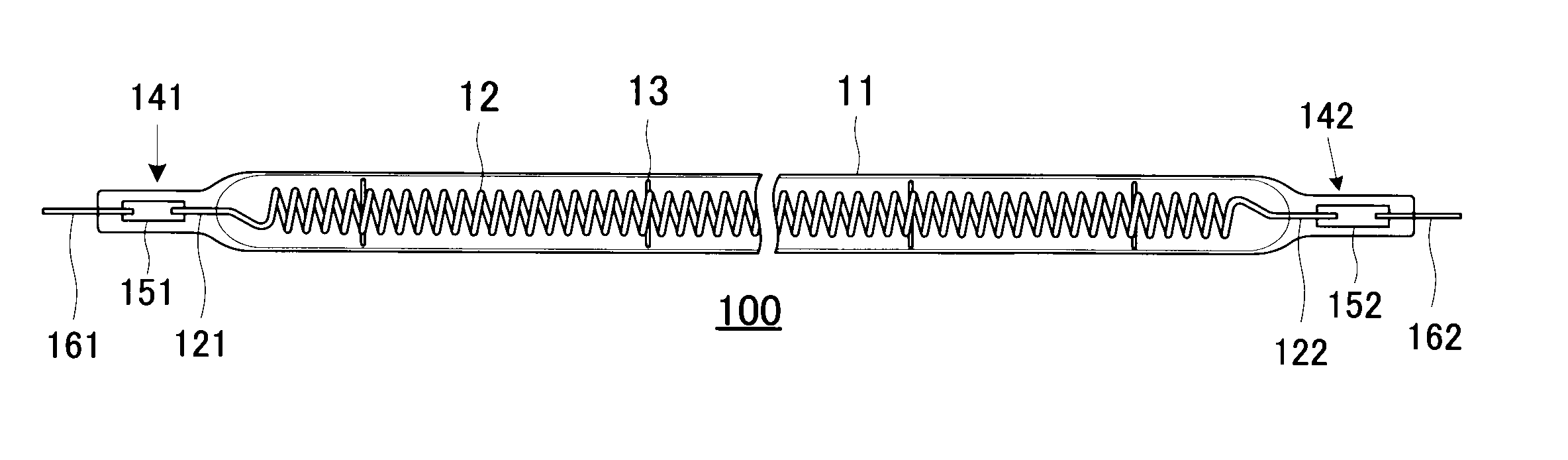
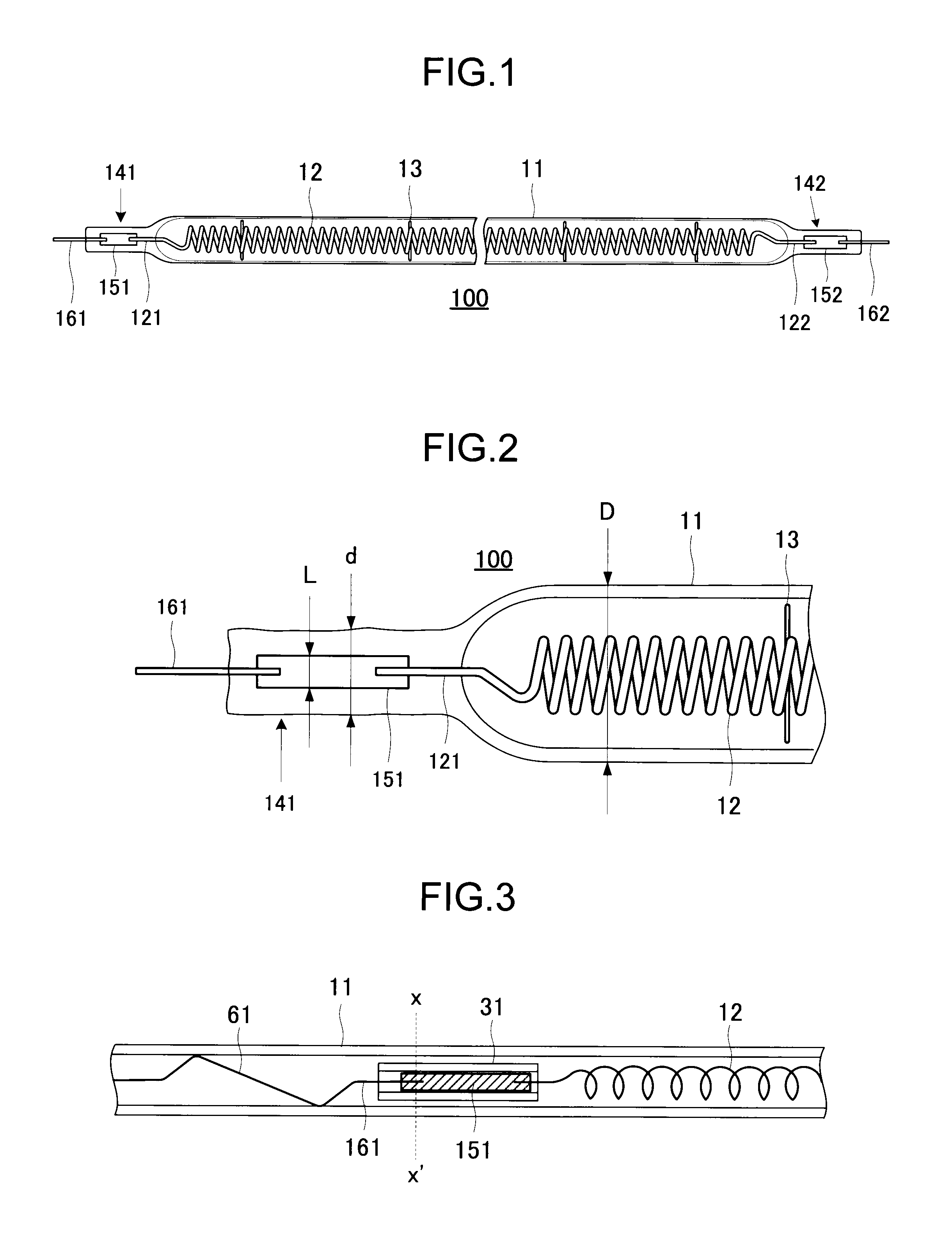
[0081]FIG. 1 is a configuration view, and FIG. 2 is an enlarged view of the essential part of FIG. 1 to illustrate a halogen lamp of the present invention.

[0082]In FIG. 1, 100 is a halogen lamp which is a type of tubular incandescent lamp. For example, the halogen lamp 100 is often used as a heater for fixing and has a bulb 11 of quartz glass or the like having radioparency. A tungsten filament 12 which is an example of an electric resistance wire made of a refractory metal is housed concentrically as a heat source in the bulb 11. The filament 12 is held in a concentric state with respect to the bulb 11 by molybdenum anchors 13 which are arranged in plural in the axial direction within the bulb 11.

[0083]In the bulb 11, inert gas such as argon Ar or nitrogen N2 is sealed under pressure of about 0.9×10⁵ Pa (Pascals) at normal temperature of 25° C. together with a mixture of a very small amount of halogen substances such as bromine Br and chlorine Cl. Both ends of the bulb 11 in its ax...

third embodiment

[0113]FIG. 11 through FIG. 14 are used to describe the halogen lamp of the invention. FIG. 11 is a configuration view, FIG. 12 is a configuration view illustrating the essential part of FIG. 11 in an enlarged state, FIG. 13 is a left side view of FIG. 12, and FIG. 14 is a perspective view of FIG. 12.

[0114]In FIG. 11 and FIG. 12, 100 is a halogen lamp which is a type of tubular incandescent lamp. For example, the halogen lamp 100 is often used as a heater for fixing and has a bulb 11 of quartz glass or the like having radioparency. A tungsten filament 12 which is an example of an electric resistance wire made of a refractory metal is housed concentrically as a heat source in the bulb 11. The filament 12 is provided with a loosely wound or straight skipped part between a plurality of coil-shaped portions formed by winding a tungsten wire and an inner lead 121 at both ends and held in a concentric state with respect to the bulb 11 by anchors 13 which are arranged in plural in the axial...

fourth embodiment

[0120]FIG. 15A and FIG. 15B are perspective views illustrating the halogen lamp of the invention. FIG. 15 A and FIG. 15B correspond to FIG. 14, and like component parts are denoted by like reference numerals. FIG. 15A and FIG. 15B show only one of the sealed portions but the other sealed portion also has the same structure.

[0121]As shown in FIG. 15A, a recess portion 521 is formed to extend from an open end 51 of the sealed portion 141 to the outer lead 161 being closer to the bulb 11. The outer lead 161 extended along the axis of the sealed portion 141 is bend along the recess portion 521 in the direction indicated by arrow x in the drawing.

[0122]As shown in FIG. 15B, the outer lead 161 is shaped to extend in a direction orthogonal to the outer circumferential surface of the sealed portion 141.

[0123]In this embodiment, the outer lead 161 is also extended from the outer circumferential surface of the sealed portion 141, and an electric power supply wire or the like can be routed fro...


PUM


Abstract

A halogen lamp including a glass bulb, a filament inserted inside the bulb, a pair of metal foils, and a pair of outer leads. Each metal foil has one end welded to the filament and the other end welded to the outer lead. The metal foils are contained in glass sleeves and they are collectively inserted inside the bulb. The bulb is softened by heating and shrinks because its inside pressure is reduced to seal the metal foils therein. Since the amount of glass of each sealed portion is larger than the other portions of the bulb by the amount of the sleeve, the shape of the sealed portion is stabilized.

Description

TECHNICAL FIELD[0001]The present invention relates to a heater lamp used for fixing a toner of a copy machine, a printer and the like, and more specifically it simplifies mounting of a heater lamp and realizes saving of the lamp mounting space.BACKGROUND ART[0002]For the sealed portion of the halogen lamp used for fixing in a copy machine of JP-A 9-320547 (KOKAI) (Related art 1), it is considered to seal it by an evacuation method which prevents oxidization or breakage of a metal foil for sealing and does not need a chip tube used for sealing of gas or the like.[0003]Since the related art 1 needs to decrease a thermal capacity to increase a lamp efficiency, its bulb has a thickness of about 1 mm. The bulb having such a thickness has disadvantages that when it is undergone the reduced-pressure sealing, the shrinkage of the bulb is not suppressed by the metal foil, a sealed portion becomes flat, a sealed shape is not stabilized, the center line of the sealed portion is largely displac...

Claims


Application Information

Patent Timeline
IPC IPC(8): H01J61/36H01K1/50H01J9/00G03G15/20
CPCH01J5/38H01J5/46H01K1/14H01K1/24H05B3/009H01K1/40H01K1/44H01K1/46H01K3/26H01K1/38
Inventor WATANABE, AKIOOOTANI, TETSUOSAKAMOTO, SEIJINISHIZONO, MINORU
Owner HARISON TOSHIBA LIGHTING CORP
Why Eureka
Try Eureka