
Device for feeding combustion air to an engine of an aircraft

a technology for combustion air and aircraft engines, which is applied in the direction of machines/engines, mechanical equipment, transportation and packaging, etc., can solve the problems of inability to clean, and inability to meet the requirements of maintenance, etc., and achieve the effect of reducing engine wear and simple technical means

Active Publication Date: 2010-03-18
AIRBUS HELICOPTERS DEUT GMBH
View PDF7 Cites 15 Cited by
  • Summary
  • Abstract
  • Description
  • Claims
  • Application Information

AI Technical Summary

Benefits of technology

[0008]An aspect of the present invention is to provide an efficient device for feeding combustion air to an engine of an aircraft with simple technical means ensuring minimum engine wear but nevertheless providing an adequate air supply in emergency operation.
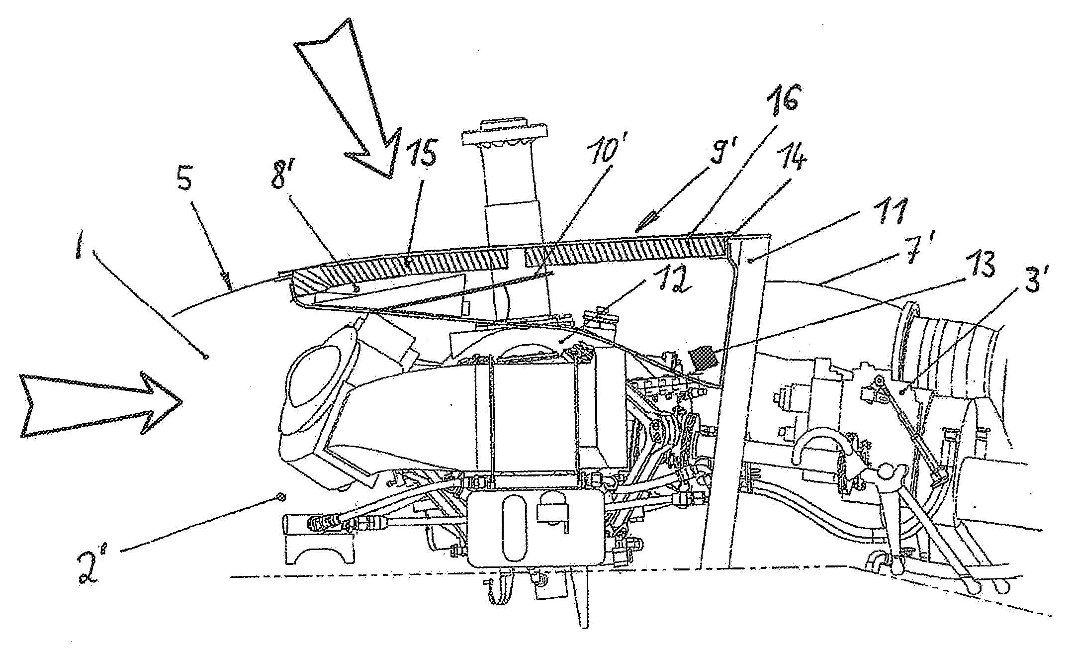
[0010]The solution according to the invention provides an advantage in particular in that by way of the further air inlet duct, in other words the reserve air inlet duct, which can comprise an inlet-cover filter element in the same manner as the primary air-inlet duct, in the case of an emergency an adequate quantity of combustion air can reach the engine. This measure improves operational safety of the aircraft because the performance of an engine is ensured in every case. In order to implement the measure according to the invention, it is merely necessary to affix a further inlet-cover filter element at a suitable position on the exterior surface of the cell of the aircraft, and to connect it to the air inlet of the engine by way of an air inlet duct.
[0016]As a preferred embodiment it is proposed that two further air inlet ducts, each with associated end inlet-cover filter elements, are arranged opposite each other on both longitudinal sides of the exterior surface, where the longitudinal sides extend between fore and aft. This design is particularly suitable in the case of smaller helicopters because the lateral surfaces of the engine deck usually provide sufficient space to arrange the additional inlet-cover filter elements. Furthermore, this design and arrangement allows quite short air inlet ducts to the engine. In this design the air inlet ducts can be detachably attached to the firewall, which, for safety reasons, is advantageously affixed directly to the engine, which minimises installation expenditure.
[0019]Since the air inlet duct usually extends adjacent to the engine, it is proposed that said air inlet duct be produced from a high-temperature-resistant BMI-(bismaleimide) material or material mixture with a component thereof and the addition of further materials, in particular carbon fibres. Apart from its high temperature resistance, this material also features a low specific weight and can be made to adapt in a simple manner to the different shapes of air inlet ducts.

Problems solved by technology

After a certain period of time the filter body of the inlet-cover filter element is usually blocked and requires cleaning.
In such a single engine inlet, performance loss due to the pressure loss resulting from the filter body that is installed upstream will practically be unavoidable.
Dangerous hazard conditions arise in particular when icing of the filter body results in total air impermeability.
This emergency measure is associated with a disadvantage in that engine wear cannot be avoided.
If the above-mentioned emergency situation arises, and if at the same time the air from the environment is severely contaminated with coarse dirt particles, emergency operation can directly lead to situations in which the engine sustains considerable damage.
Most of the time this results in severe inlet losses to the engine.
Since it must always be ensured that the available performance exceeds the maximum weight of the helicopter, this inlet loss is a limiting factor.

Method used


Image

  • Device for feeding combustion air to an engine of an aircraft
  • Device for feeding combustion air to an engine of an aircraft
  • Device for feeding combustion air to an engine of an aircraft

Examples


Embodiment Construction

[0028]In the following description and in the figures, for the purpose of avoiding repetition, the same reference characters are used for identical components, provided no further differentiation is required or sensible.

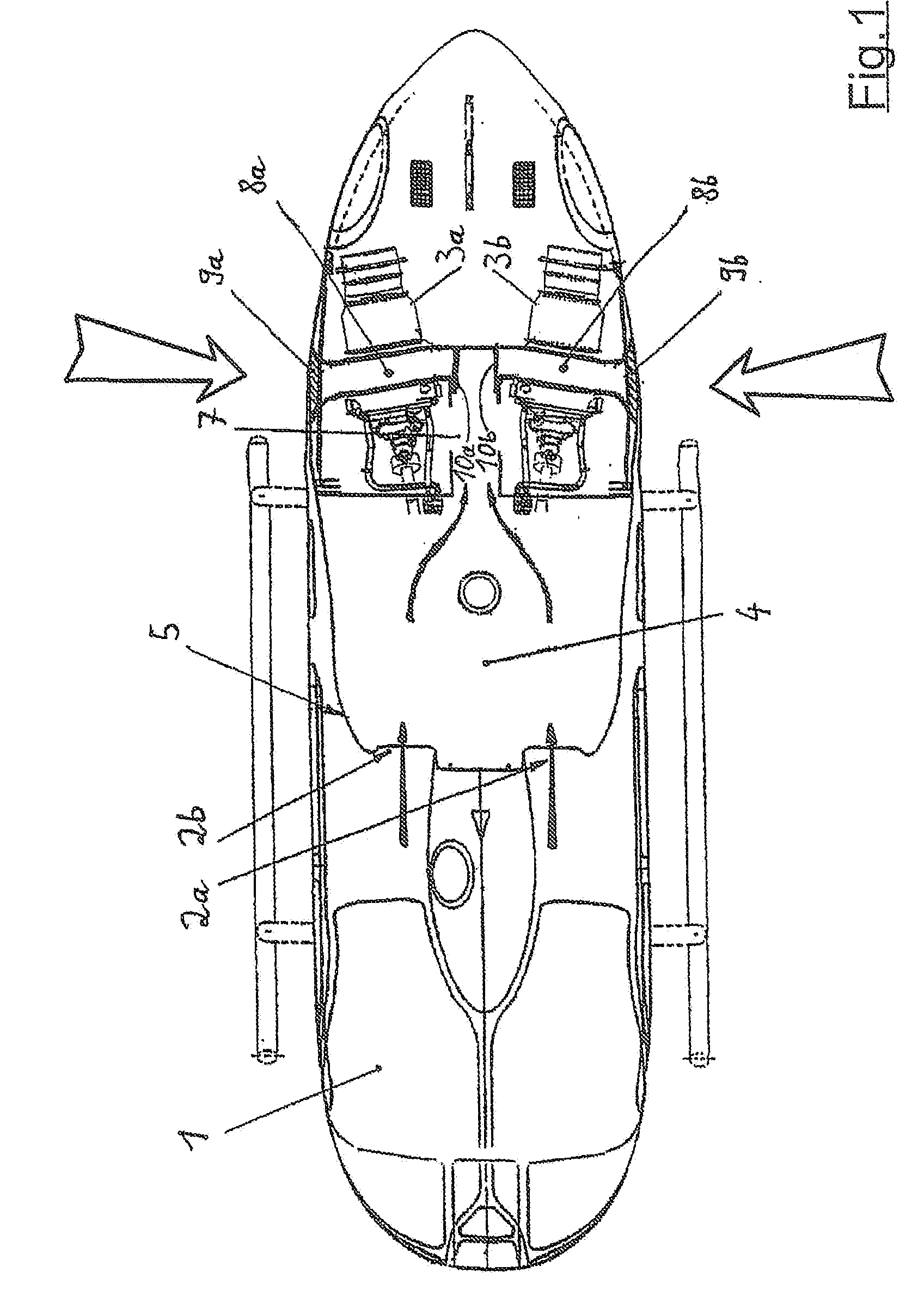
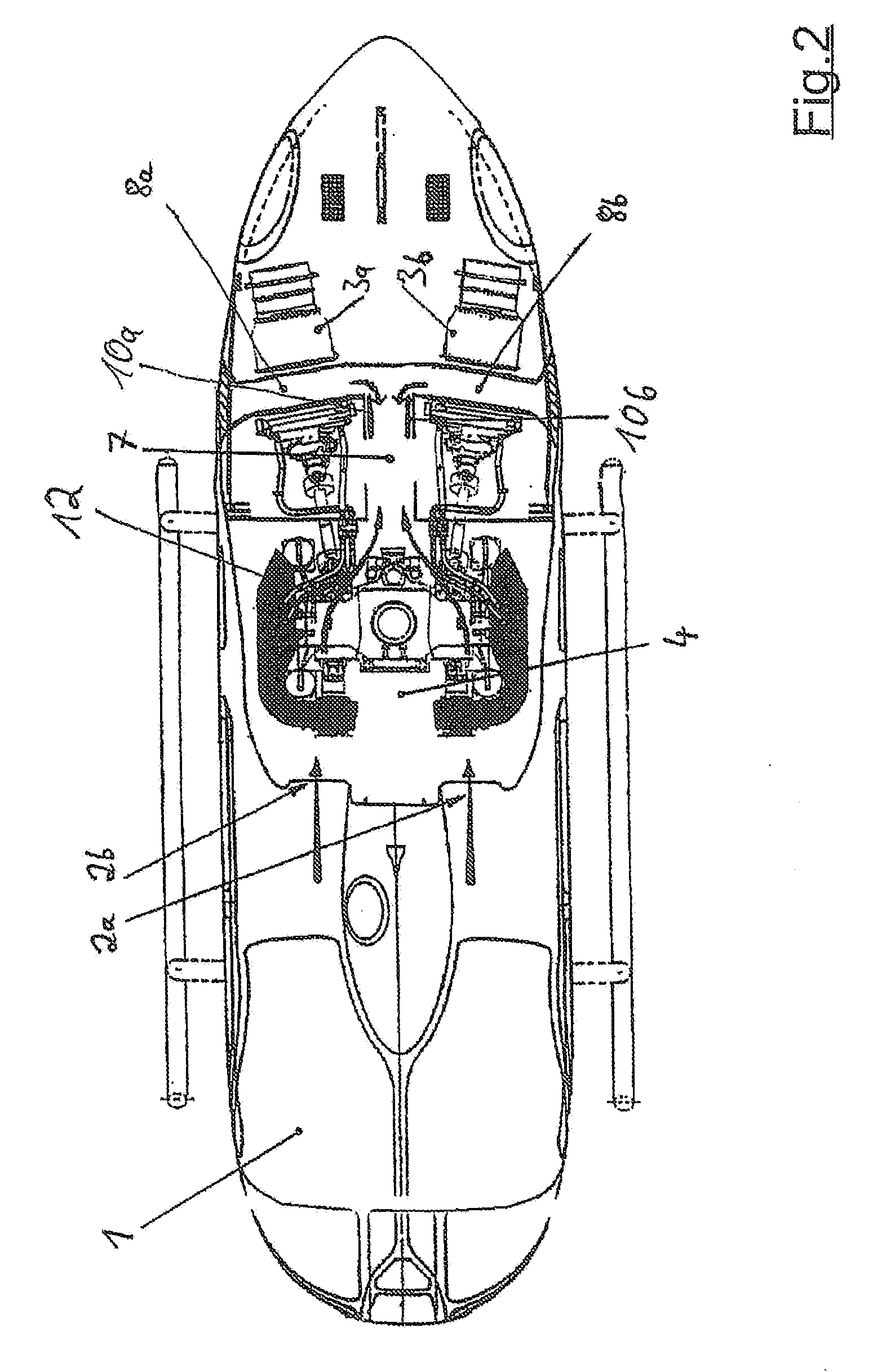
[0029]According to FIG. 1 in the upper part of a cell 1 of a helicopter there is a left-hand air inlet 2a and a right-hand air inlet 2b arranged adjacent to it, with both air inlets being used in normal operation. From the environment, combustion air flows to an engine 3a and an engine 3b arranged in the interior of the cell 1. A primary air-inlet duct 4, which starts at the air inlets 2a and 2b, passes through a main gearbox (not shown in detail in the illustration) of the helicopter.

[0030]In order to implement a two-way airstream concept, apart from the air inlet duct 4 that leads into a central duct 7 near the engine, two further air inlet ducts 8a and 8b each with associated inlet-cover filter elements 9a and 9b are arranged opposite each other on both longitudin...


PUM


Abstract

A device for feeding combustion air to an engine disposed in an interior of an aircraft is comprised of an air inlet duct extending between an exterior surface of the aircraft and the engine, wherein the air inlet duct extends from air inlets disposed in a first region of the exterior surface; at least one further air inlet duct extending between a second region of the exterior surface and the engine, so as to provide a two-way airstream supply; and a control device configured to switch the air supply to the engine to the at least one further air inlet duct when a blockage occurs in the air inlets.

Description

[0001]Priority is claimed to German Patent Application No. DE 10 2008 017 962.0, filed on Apr. 8, 2008, the entire disclosure of which is incorporated by reference herein.[0002]The present invention relates to a device for feeding combustion air to an engine of an aircraft, comprising a primary air-inlet duct, which extends between the exterior surface of the aircraft and an air inlet of the engine that is arranged in the interior and comprises an inlet-cover filter element in the region of the exterior surface.[0003]The field of application of the present invention primarily extends to aircraft in the form of helicopters. In order to drive the rotor, an engine is housed within the cell of a helicopter. The engine is designed as an internal combustion engine that receives the air that is required for combustion from the environment. For this purpose a device according to the invention for feeding combustion air is arranged between the engine and an air inlet of the cell of the helic...

Claims


Application Information

Patent Timeline
IPC IPC(8): F16K11/052
CPCF02C7/052B64D33/02B64C27/04F05D2220/329Y10T137/86847
Inventor OSSWALD, BERNDMACCHI, SERGE
Owner AIRBUS HELICOPTERS DEUT GMBH
Learn More