
Particle reduction in pecvd processes for depositing low-k material by using a plasma assisted post-deposition step

a technology of pecvd and post-deposition step, which is applied in the direction of chemical vapor deposition coating, coating, metallic material coating process, etc., can solve the problems of reduced mechanical stability, deposition-related failures may be observed, and may not be compatible with defect criteria of semiconductor devices having critical dimensions of 50 nm and less, so as to improve chemical vapor deposition and reduce the defect rate , the effect of reducing the exposure to reactive components

Inactive Publication Date: 2010-03-04
ADVANCED MICRO DEVICES INC
View PDF7 Cites 15 Cited by
  • Summary
  • Abstract
  • Description
  • Claims
  • Application Information

AI Technical Summary

Benefits of technology

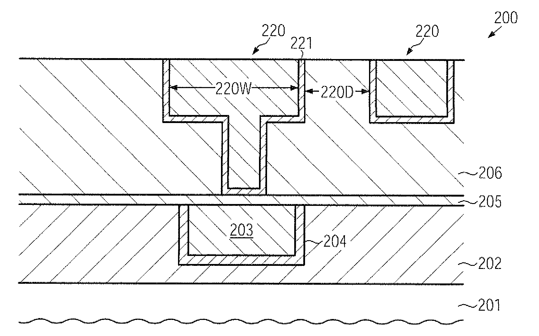
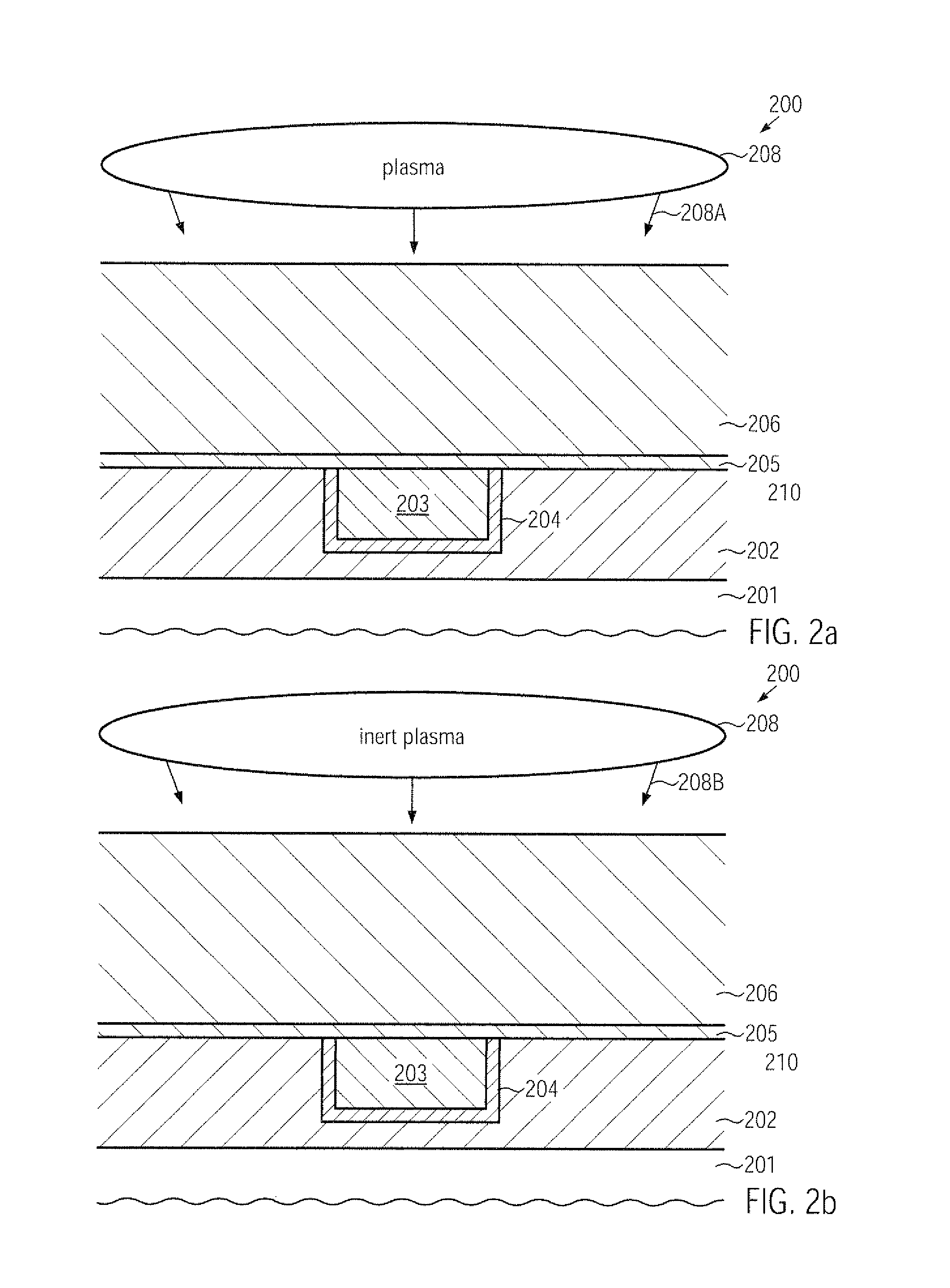
[0016]Generally, the present disclosure relates to techniques for forming sophisticated low-k dielectric materials on the basis of plasma enhanced chemical vapor deposition (PECVD) processes, wherein a significantly reduced defect rate may be obtained after the deposition of the low-k dielectric material. Without intending restriction of the present application to the following explanation, it is assumed that the presence of reactive species in the deposition ambient after discontinuing the plasma have significant influence on the creation of corresponding particles. According to the principles disclosed herein, it is contemplated to reduce exposure to reactive components after discontinuing the supply of the material of specific precursor species by establishing an inert plasma ambient, thereby reducing the effect of any reactive components that may still be present in the ambient prior to essentially completely removing the precursor species after the deposition phase. An inert plasma ambient is to be understood as an ambient in which a plasma may be established on the basis of gaseous components, which may not result in a chemical reaction with the dielectric material deposited during the preceding deposition phase. Consequently, by implementing an additional inert plasma treatment after the actual plasma enhanced deposition process, enhanced surface conditions may be provided for the low-k dielectric material, thereby enabling application of well-established PECVD low-k dielectric materials for sophisticated semiconductor devices requiring metallization systems with interlayer dielectric materials of a dielectric constant of 2.7 and significantly less.

Problems solved by technology

For extremely scaled integrated circuits, the signal propagation delay is no longer limited by the circuit elements, for instance by field effect transistors, but is limited, owing to the increased density of circuit elements, which requires an even more increased number of electrical connections for mutually connecting these circuit elements, by the close proximity of the metal lines, since the line-to-line capacitance increases as the spacing decreases.
However, in very advanced semiconductor devices with reduced distances between neighboring metal lines, such as the 45 nm technology node, the resulting parasitic RC time constants may still be considered inappropriate, thereby requiring even lower values for a dielectric constant of the inter metal dielectric material.
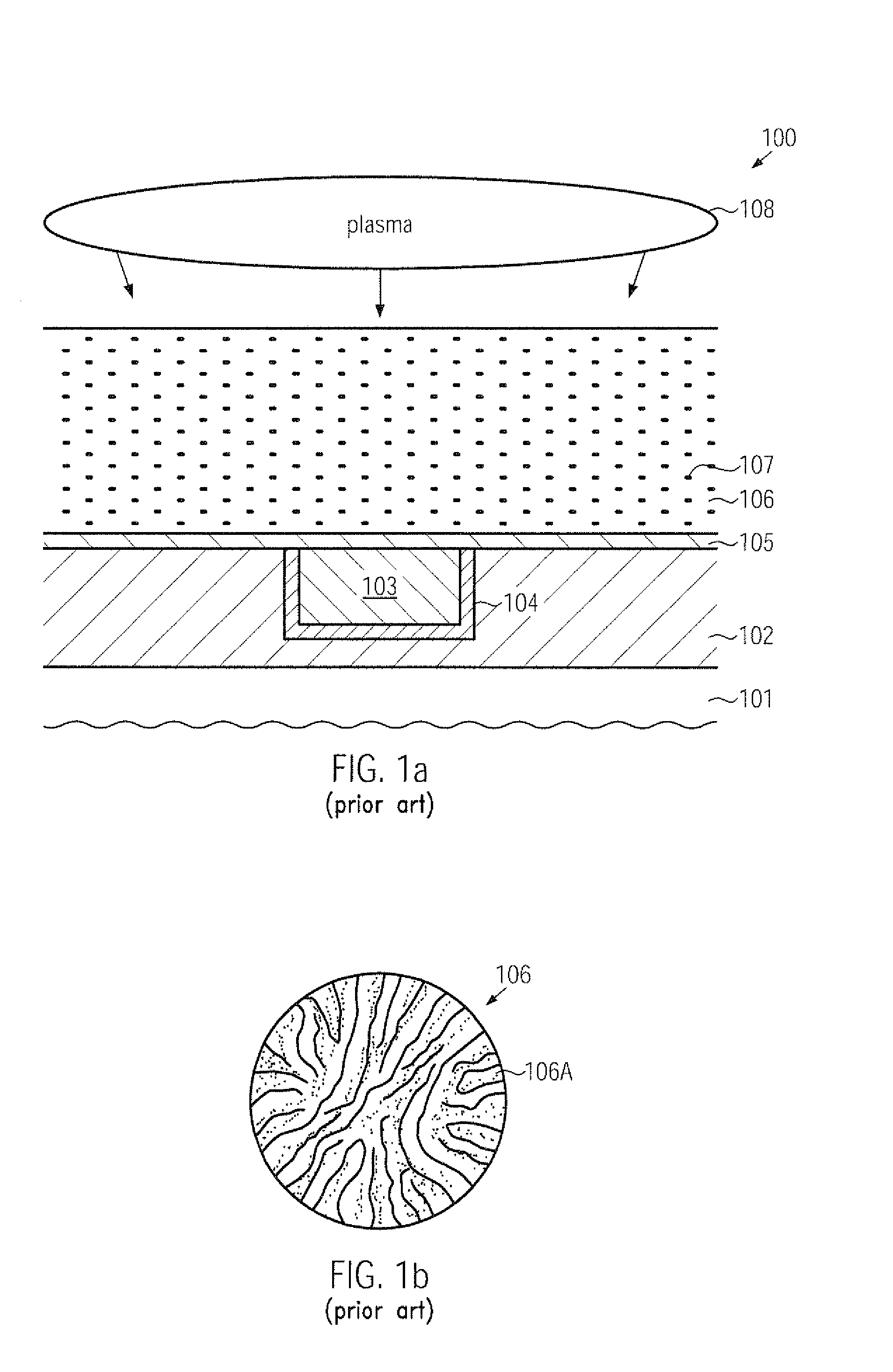
Although the deposition of low-k dielectric materials, which may have per se a very low dielectric constant or which may be converted in ultra low-k materials by subsequent treatment, by means of plasma enhanced CVD techniques presents a very promising approach for sophisticated semiconductor devices, it turns out, however, that, in addition to general issues related to dielectric materials of reduced permittivity, such as reduced mechanical stability and the like, deposition-related failures may be observed which may not be compatible with defect criteria of semiconductor devices having critical dimensions of 50 nm and less, as will be described in more detail with reference to FIGS. 1a-1b.
After the deposition of the low-k dielectric material 106, a plurality of surface defects in the form of particles may be observed, wherein the large number of the corresponding particles may not be compatible with the defect control requirements of sophisticated technology flows, since excessive chemical cleaning of the layer 106 may result in additional damage to exposed surface portions of the layer 106, while less efficient and thus less aggressive cleaning processes may result in an unacceptable defect density.
As shown, areas of increased particle density 106A may extend across significant surface areas of the layer 106, thereby requiring efficient post-deposition cleaning recipes which, however, may result in a certain degree of surface damage in the layer 106, thereby resulting in reduced performance and reliability of the metallization system of the semiconductor device 100.
Consequently, although plasma enhanced CVD techniques may represent promising techniques for forming low-k dielectric materials and ultra low-k dielectric materials, the high defect rate observed after the deposition may not be compatible with defect control requirements of advanced technology nodes or may result in reduced performance and reliability of respective metallization structures.

Method used


Image

  • Particle reduction in pecvd processes for depositing low-k material by using a plasma assisted post-deposition step
  • Particle reduction in pecvd processes for depositing low-k material by using a plasma assisted post-deposition step
  • Particle reduction in pecvd processes for depositing low-k material by using a plasma assisted post-deposition step

Examples


Embodiment Construction

[0029]Various illustrative embodiments of the invention are described below. In the interest of clarity, not all features of an actual implementation are described in this specification. It will of course be appreciated that in the development of any such actual embodiment, numerous implementation-specific decisions must be made to achieve the developers' specific goals, such as compliance with system-related and business-related constraints, which will vary from one implementation to another. Moreover, it will be appreciated that such a development effort might be complex and time-consuming, but would nevertheless be a routine undertaking for those of ordinary skill in the art having the benefit of this disclosure.

[0030]The present subject matter will now be described with reference to the attached figures. Various structures, systems and devices are schematically depicted in the drawings for purposes of explanation only and so as to not obscure the present disclosure with details ...


PUM

PropertyMeasurementUnit
dielectric constantaaaaaaaaaa
pressureaaaaaaaaaa
distanceaaaaaaaaaa

Abstract

When forming dielectric materials of reduced dielectric constant in sophisticated metallization systems, the creation of defect particles on the dielectric material may be reduced during a plasma enhanced deposition process by inserting an inert plasma step after the actual deposition step.

Description

BACKGROUND OF THE INVENTION[0001]1. Field of the Invention[0002]Generally, the present disclosure relates to the fabrication of integrated circuits, and, more particularly, to the formation of dielectric material layers of reduced permittivity.[0003]2. Description of the Related Art[0004]Semiconductor devices and any other microstructures are typically formed on substantially disc-shaped substrates made of any appropriate material. The majority of semiconductor devices including highly complex electronic circuits are currently, and in the foreseeable future will be, manufactured on the basis of silicon due to the virtually unlimited availability of silicon, thereby rendering silicon substrates and silicon-containing substrates, such as silicon-on-insulator (SOI) substrates, viable carriers for forming semiconductor devices, such as microprocessors, SRAMs, ASICs (application specific ICs) and the like. The individual integrated circuits are arranged in an array, wherein most of the m...

Claims


Application Information

Patent Timeline
Patent Type & Authority Applications(United States)
IPC IPC(8): H01L21/3205H01L21/3105
CPCC23C16/401C23C16/56H01L21/02126H01L21/31633H01L21/02274H01L21/0234H01L21/02348H01L21/02203
Inventor MAYER, ULRICHRUELKE, HARTMUT
Owner ADVANCED MICRO DEVICES INC
Learn More