
Polymer seaming with diffusion welds

a technology of diffusion welds and polymer films, applied in the field of polymer films, can solve the problems of ineffective melt welding in joining separate pieces, prone to mechanical tears, rips, other damages, and easy mechanical tear and contamination of thin sheets, so as to prevent thermal deformation, reduce the propagation of tear, and increase the modulus of adhesives

Active Publication Date: 2010-03-04
NEXOLVE
View PDF3 Cites 3 Cited by
  • Summary
  • Abstract
  • Description
  • Claims
  • Application Information

AI Technical Summary

Benefits of technology

[0023]One advantage of the present invention is that a seam created by the disclosed invention exhibits decreased tear propagation at the seam points. Another advantage is that the present invention eliminates the need for adhesives to join two materials. This prevents thermal deformations due to inherent CTE differences of the materials and the adhesive. These thermal deformations can present challenges at temperatures below the Tg of adhesives when the modulus of the adhesives tends to increase. Another advantage is that characteristic conductivity of conductive materials, such as carbon-filled polyimide, is retained at the seaming point.
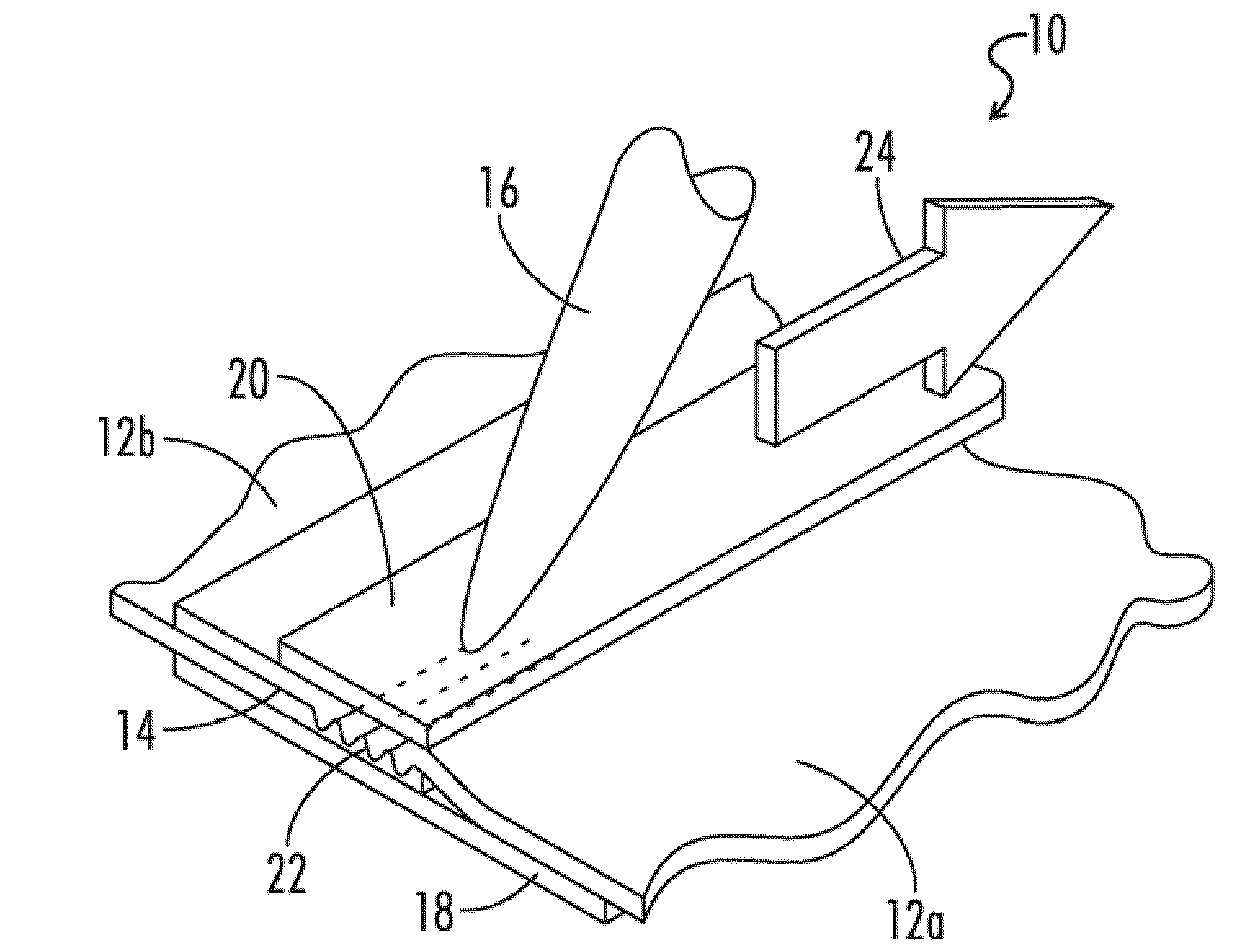
[0024]In one embodiment of the present invention, the polymeric materials are heated by contact with a heating tool that also applies pressure to the interface. FIG. 1 shows one example of a thermal seaming system 10 that uses a heated stylus 16. A first sheet of a polymeric material 12a and a second sheet of polymeric material 12b are positioned with their respective faying surfaces forming an overlapping interface 14. The overlapped interface 14 can be about one inch across, but wider overlaps allow more area for a larger diffusion weld, and smaller overlaps can also be used. The interface 14 is placed on an insulative backing 18 and a protective overlay 20 can be placed over the top of the interface 14. The heated stylus 16 is then dragged 24 across the overlay 20. The stylus 16 applies both heat and pressure to the interface 14 and forms a continuous diffusion weld 22.
[0025]FIG. 2 shows an alternative thermal seaming system embodiment 30 of the present invention that utilizes a heated wheel 32. In this embodiment, a heated wheel 32 is rolled 34 across the interface 14 to apply both heat and pressure that forms a continuous diffusion weld 22. While this embodiment is shown without a protective overlay, it should be understood that embodiments exist for diffusion welding with or without a protective overlay. The need for a protective overlay is determined by experimentation based on several factors, including the materials being diffusion welded, the thickness of the materials, the type of apparatus applying the heat and pressure, the diffusion welding temperature and pressure used, and the application time for the temperature and pressure application.
[0026]FIG. 3 shows yet another thermal seaming system embodiment 40 of the present invention that utilizes a plurality of heated plungers 42. Alternate embodiments could use a single heated plunger 42. In this embodiment, the heated plungers 42 move intermittently in vertical 44 and horizontal 46 directions applying heat and pressure at various points along the interface 14. The effect is to create multiple “spot” diffusion welds 48. The plungers 42 apply heat and pressure to produce spot diffusion welds 48, and then move vertically 44 out of contact with the interface 14. The plungers 42 then move horizontally 46 to re-position themselves for the next spot diffusion welds 48. Then the plungers 42 move vertically 44 downward into contact with the interface 14, and produce the next spot diffusion welds 48 by applying heat and pressure. Reference to the plunger 42 moving horizontally or vertically means the plunger motion includes a horizontal or vertical component, so the plunger 42 can move both horizontally and vertically at the same time. Vertical motion is used to contact or separate the plunger 42 from the interface, and horizontal motion is used to re-position the plunger 42 for another spot diffusion weld 48.
[0027]The plungers 42 can be used to produce spot diffusion welds 48, instead of the continuous diffusion welds discussed above. The plungers 42 could also be dragged to produce continuous diffusion welds, or a mixture of spot and continuous diffusion welds, as desired. The plungers 42 can provide simpler temperature control mechanisms, because the diffusion welding process is intermittent and focused at the end of the plunger 42. Also, the contact end of the plunger 42 can have a small area, so a high pressure can be applied at the spot of the diffusion weld. However, the spot diffusion welds 48 may not produce a complete seal between the first and second polymeric sheets 12a, 12b. Each spot diffusion weld 48 may be isolated from every other spot diffusion weld 48, meaning each spot diffusion weld 48 does not contact any other spot diffusion weld 48. When the spot diffusion welds 48 are isolated, a complete seal may not be formed between the first and second polymeric sheets 12a, 12b,
[0028]Most welds of materials with a non-zero CTE have differential shrinkage distortion of the joined bodies upon cooling. This is the result of temperature gradients which are characteristic in practically all welding techniques. This distortion is undesirable for many applications using diffusion welded thin film membranes. It can be reduced by locally tensioning the sheets of polymeric material 12a, 12b in the vicinity of the diffusion weld during the welding process. When the tension is released, the local residual compression stress tends to counteract the local residual tensile stresses that result from the weld. FIG. 4 shows one embodiment of the thermal seaming system 50 that utilizes a heated plunger 42 in conjunction with a local tensioner 52. In this embodiment, the tensioner 52 is circular-shaped. The plunger 42 contacts the interface 14 through a tensioner opening 54 to create the diffusion weld 48.

Problems solved by technology

Thin sheets are often sensitive to mechanical tears and contamination.
Some materials are not as strong as others, so thin sheets are even more prone to mechanical tears, rips, or other damages.
Because thermoset plastics do not have a true melting point, or they begin to decompose as they approach their melting point, melt welding is not effective in joining separate pieces.
If two different materials are joined together, and the different materials have different coefficients of thermal expansion (CTEs), the rapid and large temperature changes can cause the materials to separate.
However, the application of the adhesive seaming chemicals is challenging and prone to contamination.
Additionally, commonly used adhesives, such as acrylic-based or silicone-based, lose mechanical strength and increase in stiffness at temperatures below their glass transition temperature (Tg), such as temperatures encountered in space.
Differences in the CTE between the polymer and the adhesive can also lead to premature seam failure.
A mechanical fastener, such as stitching with thread, is prone to tearing especially if single layers of materials are seamed together.

Method used


Image

  • Polymer seaming with diffusion welds
  • Polymer seaming with diffusion welds
  • Polymer seaming with diffusion welds

Examples


working examples

[0053]Specific working examples are provided below to further clarify specific embodiments of the current invention.

example 1

[0054]Spot diffusion welds were produced in an overlapping seam between a 2 mil thick polyimide film associated with the trademark KAPTON HN and another 2 mil thick polyimide film associated with the trademark KAPTON HN. The overlapping seam was held in place by magnets placed above and below the seam such that the magnets were drawn towards each other. A backing was positioned under the seam such that the plunger presses the seam directly into the backing. The backing was formed of a 1 / 1000 inch thick KAPTON tape secured with a silicon pressure sensitive adhesive to a 1 / 16 inch thick ceramic wick. The 1 / 16 inch ceramic wick was positioned over a ⅛ inch thick nylon sheet, which was positioned over a rubber foam.

[0055]A plurality of heated plungers was pressed into the polyimide material at the seam, such that the polyimide seam was positioned directly between the heated plungers and the backing. The heated plungers had a tip with a 0.145 inch diameter circle, and the tip was heated ...

example 2

[0056]Spot diffusion welds were produced in an overlapping seam between a 2 mil thick polyimide film associated with the trademark KAPTON E and another 2 mil thick polyimide film associated with the trademark KAPTON E. The same process and parameters as described for Example 1 was used in Example 2.


PUM

PropertyMeasurementUnit
thickaaaaaaaaaa
thicknessaaaaaaaaaa
thicknessaaaaaaaaaa

Abstract

The present invention is a method for seaming a polymeric material. The method involves forming an interface between a plurality of separate polymeric sheets of materials. Next, heat and pressure are applied to facilitate the diffusion of the polymer molecules at the interface. A diffusion weld is made when the polymer molecules diffuse across the interface.

Description

[0001]This application is a continuation in part of, and claims priority to, pending U.S. patent application Ser. No. 11 / 740,267, which was filed on Apr. 25, 2007.BACKGROUND OF THE INVENTION[0002]1. Field of the Invention[0003]The invention relates generally to the manufacture of polymer films. More specifically, the invention relates to polymer films that have been seamed and a method of seaming sheets of polymeric material together with diffusion welding.[0004]2. Background Art[0005]Polymer films are frequently produced in a rolled form. Such rolls are often seamed together to combine multiple rolls, to make a longer roll, or to make a larger polymeric sheet structure. The films can be thin, such as 2 mils thick or less, but the films can also be thicker. Thin sheets are often sensitive to mechanical tears and contamination. Some materials are not as strong as others, so thin sheets are even more prone to mechanical tears, rips, or other damages.[0006]Thermoset plastics are polyme...

Claims


Application Information

Patent Timeline
Patent Type & Authority Applications(United States)
IPC IPC(8): B32B3/04B29C65/02
CPCB29C65/006B29C65/02B29C65/18B29C66/0044B29C66/1122B29C66/1142B29C66/21B29C66/232B29C66/303B29C66/344B29C66/348B29C66/43B29C66/71B29C66/712B29C66/723B29C66/73111B29C66/73115B29C66/80B29C66/836B29C66/8362B29C66/919B29C66/91935B29C66/91943B29K2027/18B29K2065/00B29K2067/00B29K2071/00B29K2077/00B29K2079/08B29K2079/085B29K2081/04B29K2101/10B29K2105/0079B29L2009/00B29L2031/3097B64G1/226B64G1/407B64G1/44B64G1/54C08G73/1046C08G73/105C08G73/1067C08G73/1071C08G73/22C08L79/04C08L79/08B29C66/7394B29C66/91411B29C66/91421B29C66/81422B29C66/91941B29C66/91945B29C66/435Y10T428/197Y10T428/19B29C65/00B29C66/73921B29C66/73941B29C66/72321B29C66/73112B29K2079/00
Inventor LAUE, GREGORYCLAYTON, WILLIAMJOHNSON, MARKWRIGHT, TIMOTHYMELTON, KEVINPOE, GARRETT
Owner NEXOLVE
Learn More