
Touch panel, display, and manufacturing method of touch panel

a manufacturing method and touch panel technology, applied in the manufacture of electric discharge tubes/lamps, instruments, computing, etc., can solve the problems of defective signal transmission of conventional touch panels b>100/b>, poor sensing sensitivity, and disadvantages of calculation of touch positions, etc., to achieve low parasitic capacitance, low transmission resistance, and good sensing sensitivity.

Inactive Publication Date: 2010-02-25
AU OPTRONICS CORP
View PDF3 Cites 102 Cited by
  • Summary
  • Abstract
  • Description
  • Claims
  • Application Information

AI Technical Summary

Benefits of technology

"The present invention provides a touch panel with low sheet resistance and low parasitic capacitance, which solves issues in conventional touch panels. The touch panel has a substrate and includes a first sensing series and a second sensing series. The first sensing series includes a plurality of first sensing pads and at least one first bridge line, while the second sensing series includes at least one second sensing pad. The first bridge line connects two adjacent first sensing pads, and the material of the first bridge line is different from the material of the first sensing pads. The second bridge line connects two adjacent second sensing pads, and the material of the second bridge line is also different from the material of the second sensing pads. The touch panel also includes a first dielectric layer and a second dielectric layer to cover the first and second sensing series, respectively. The touch panel further includes fan-out traces connected to the first and second sensing series. The invention provides a display with a touch panel and a display panel."

Problems solved by technology

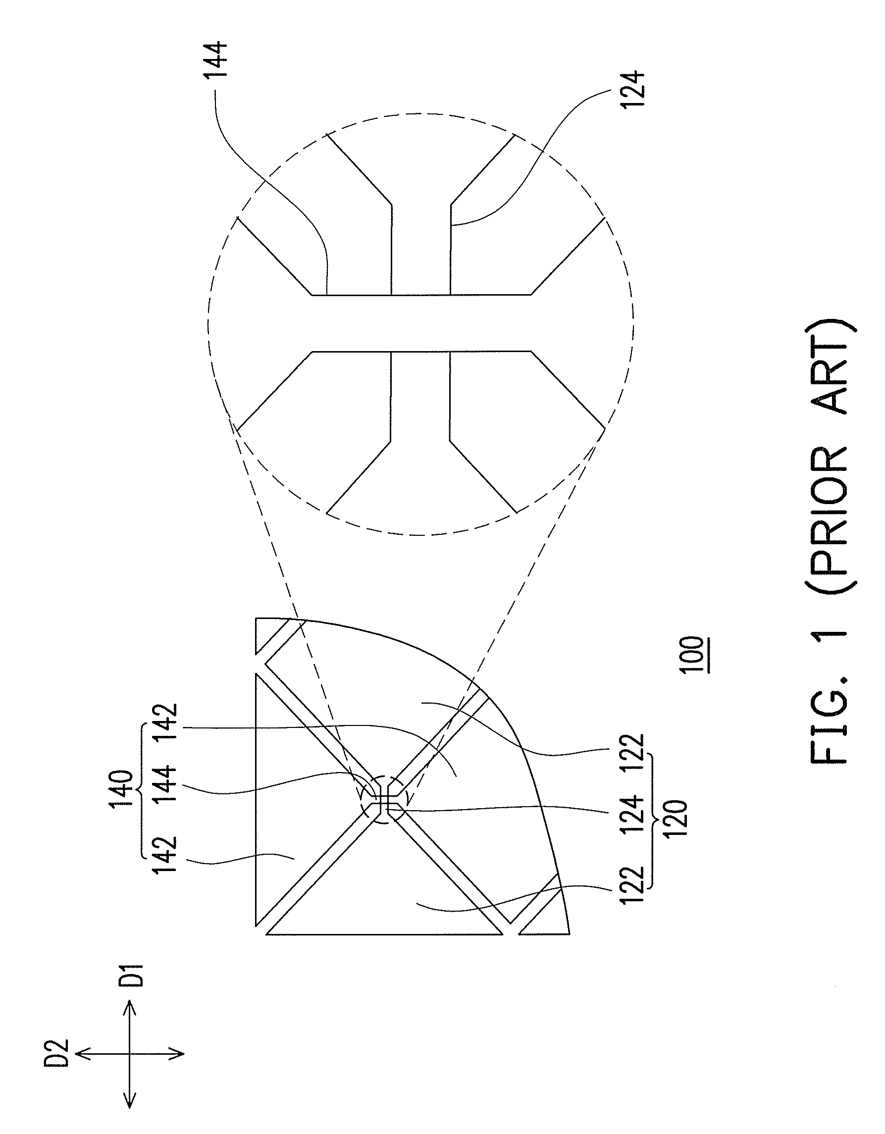
Moreover, an intersection area between the first bridge line 124 and the second bridge line 144 has a larger parasitic capacitance and thus disadvantageous to calculation of the touch position.
In other words, the conventional touch panel 100 may have issues of defective signal transmission and poor sensing sensitivity.

Method used


Image

  • Touch panel, display, and manufacturing method of touch panel
  • Touch panel, display, and manufacturing method of touch panel
  • Touch panel, display, and manufacturing method of touch panel

Examples


Embodiment Construction

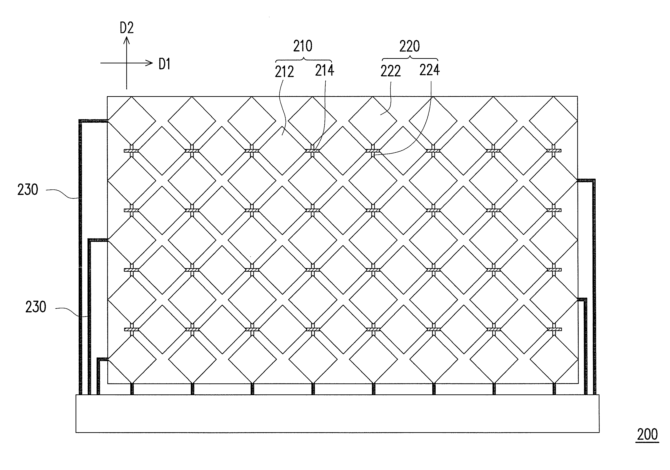
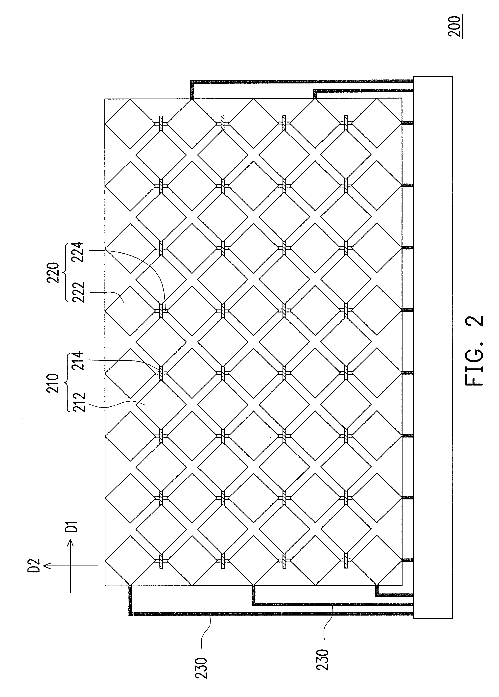
[0039]FIGS. 2 through 5 show top views of the touch panels according to the first through the fourth embodiments of the present invention. Referring to FIG. 2 first, a touch panel 200 has at least one first sensing series 210 and at least one second sensing series 220. The first sensing series 210 extends along a first direction D1. The first sensing series 210 includes a plurality of first sensing pads 212 and at least one first bridge line 214. The first bridge line 214 connects two adjacent first sensing pads 212. A material of the first bridge line 214 differs from a material of the first sensing pads 212. The second sensing series 220 extends along a second direction D2. The first direction D1 is different from the second direction D2. For example, the first direction D1 is perpendicular to the second direction D2. The second sensing series 220 includes a plurality of second sensing pads 222 and at least one second bridge line 224. The second bridge line 224 connects two adjace...


PUM


Abstract

A touch panel including a substrate, at least one first sensing series and at least one second sensing series is provided. The first sensing series is disposed on the substrate and extends along a first direction. The first sensing series includes several first sensing pads and at least one first bridge line. The first bridge line connects two adjacent first sensing pads, and a material of the first bridge line differs from a material of the first sensing pads. The second sensing series is disposed on the substrate and extends along a second direction. The first direction is different from the second direction. The second sensing series includes several second sensing pads and at least one second bridge line. The second bridge line connects two adjacent second sensing pads.

Description

CROSS-REFERENCE TO RELATED APPLICATION[0001]This application claims the priority benefit of Taiwan application serial no. 97131831, filed on Aug. 20, 2008. The entirety of the above-mentioned patent application is hereby incorporated by reference herein and made a part of this specification.BACKGROUND OF THE INVENTION[0002]1. Field of the Invention[0003]The present invention relates to a touch panel, a display and a manufacturing method of the touch panel. More particularly, the present invention relates to a touch panel and a display which have high signal transmission quality and a manufacturing method of the touch panel.[0004]2. Description of Related Art[0005]As information technology, wireless mobile communication and information appliances have been rapidly developed and applied, to achieve more convenience, more compact and light volume and more human designs, various information products have changed from using conventional input devices such as key boards or mice to using t...

Claims


Application Information

Patent Timeline
Patent Type & Authority Applications(United States)
IPC IPC(8): G06F3/041H01J9/00
CPCG06F3/044G06F3/041G06F2203/04111G06F2203/04103G06F3/0445G06F3/0446
Inventor WU, YUAN-CHUNLEE, HSIN-HUNGMA, MEI-SHENGCHENG, KUO-HSINGCHIEN, YU-FENG
Owner AU OPTRONICS CORP
Learn More