Eureka AIR delivers breakthrough ideas for toughest innovation challenges, trusted by R&D personnel around the world.

Secondary battery

a second-generation battery and battery technology, applied in the field of second-generation batteries, can solve the problems of reducing affecting the efficiency of the battery, so as to improve the productivity of the battery, improve the stability of the battery, and speed up the filling rate of the electrolyte

Inactive Publication Date: 2010-02-11
SAMSUNG SDI CO LTD
View PDF3 Cites 38 Cited by
  • Summary
  • Abstract
  • Description
  • Claims
  • Application Information

AI Technical Summary

Benefits of technology

[0011]The present invention has been made to solve the above problems, and the present invention provides a secondary battery in which a filling rate of an electrolyte is improved. The present invention also provides a secondary battery in which radiation of heat is improved. The present invention also provides a secondary battery whose shape cannot be easily distorted.
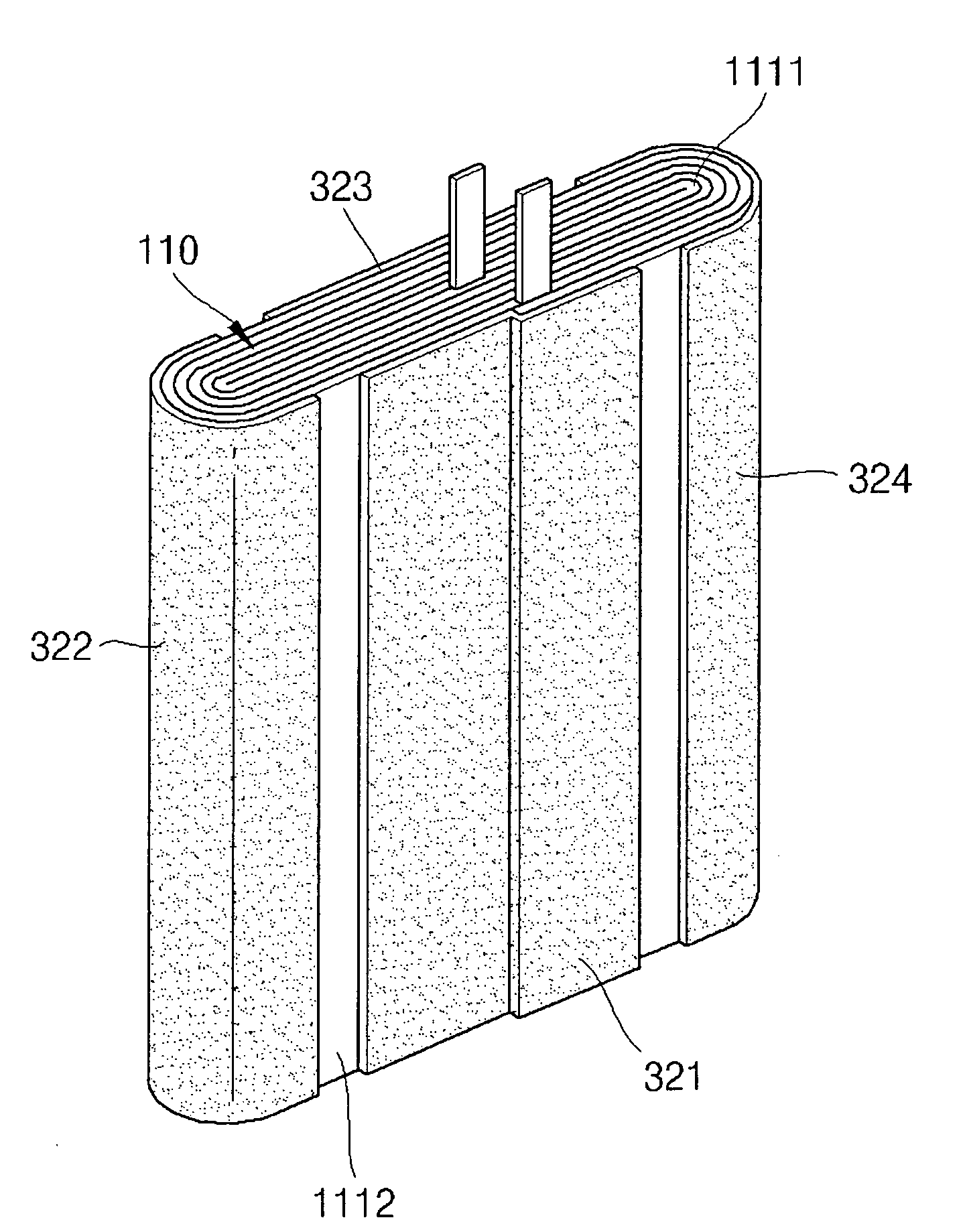
[0026]The above-mentioned secondary battery can accomplish the objects of the present invention. In particular, since separation spaces are formed between several finishing tapes, an electrolyte can rapidly move downward during injection of the electrolyte, thereby making the filling rate of the electrolyte quicker and improving the productivity of the battery. Further, since heat is radiated through the separation spaces formed between several finishing tapes, the stability of the battery is improved. Furthermore, since the finishing tapes are spaced apart by the separation spaces, the pressure applied to the electrode assembly is reduced, reducing the deformation of the electrode assembly.

Problems solved by technology

First, it hampers smooth filling of the electrolyte. In other words, the finishing tape, which is attached to the entire outer surface of the electrode assembly, impedes the flow of the electrolyte downward inside the can during injection of the electrolyte. Accordingly, the electrolyte is likely to be filled only at an upper portion of the electrode assembly, increasing process time and lowering productivity.
Second, it prevents radiation of heat. A large amount of heat is generated in the electrode assembly during charge and discharge processes of the battery, and the finishing tape attached to the entire surface of the electrode assembly prevents dissipation of the heat through the surface of the electrode assembly.
Third, it causes deformation of the battery. The electrode assembly expands during discharge of the battery. In this case, the finishing tape attached to the entire surface of the electrode assembly excessively presses the electrode assembly, abnormally deforming the shape of the battery.

Method used


Image

  • Secondary battery
  • Secondary battery
  • Secondary battery

Examples


Embodiment Construction

[0034]Hereinafter, embodiments of the present invention will be described in detail with reference to the accompanying drawings. The same reference numerals are used throughout the drawings to refer to the same or like elements. Detailed descriptions of well-known functions and structures incorporated herein may be omitted to avoid obscuring the subject matter of the present invention.

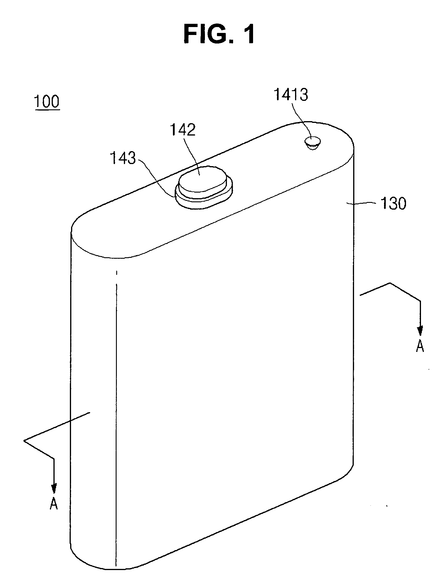
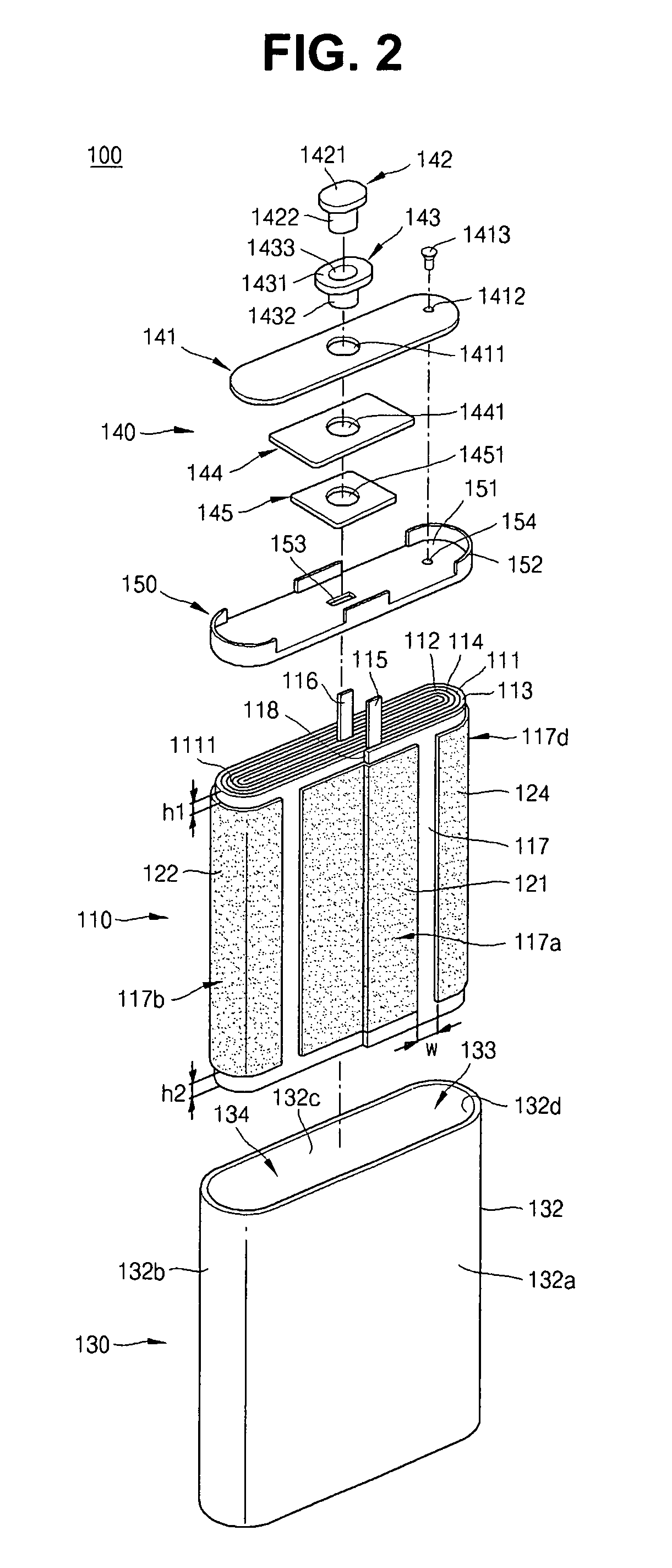
[0035]Referring to FIGS. 1 and 2, a secondary battery 100 is of a square type, and includes an electrode assembly 110, a plurality of finishing tapes 121, 122, 123, and 124, a can 130, a cap assembly 140, and an insulation case 150.

[0036]Referring to FIGS. 2 and 3, the electrode assembly 110 includes a first electrode plate 111, i.e. a positive electrode plate, a second electrode plate 112, i.e. a negative electrode plate, first and second separators 113 and 114, a first electrode tab 115, i.e. a positive electrode tab, and a second electrode tab 116, i.e. a negative electrode tab. In the electrode ass...


PUM

PropertyMeasurementUnit
total widthsaaaaaaaaaa
widthaaaaaaaaaa
structureaaaaaaaaaa

Abstract

A secondary battery includes an electrode assembly in which a first electrode plate, a separator, and a second electrode assembly are sequentially stacked forming a stack and is wound about one edge of the stack, and a plurality of finishing tapes attached to the outer surface of the electrode assembly and spaced apart from each other along the winding direction of the electrode assembly.

Description

CLAIM OF PRIORITY[0001]This application makes reference to, incorporates the same herein, and claims all benefits accruing under 35 U.S.C. §119 from an application for SECONDARY BATTERY earlier filed in the Korean Intellectual Property Office on the 6th of August 2008 and there duly assigned Serial No. 10-2008-0076981.BACKGROUND OF THE INVENTION[0002]1. Field of the Invention[0003]The present invention relates to a secondary battery, and more particularly to, a secondary battery having an electrode assembly on which finishing tapes forming passages are attached.[0004]2. Description of the Related Art[0005]Lithium secondary batteries are classified, according to their electrolytes, into lithium ion secondary batteries using liquid electrolytes and lithium polymer batteries using polymer electrolytes. A lithium ion secondary battery is manufactured by sealing a jelly-roll type electrode assembly, which is a power generation source, with a can or a pouch type cover, and then by injecti...

Claims


Application Information

Patent Timeline
Patent Type & Authority Applications(United States)
IPC IPC(8): H01M6/10H01M50/627
CPCH01M2/0217H01M2/361H01M10/052H01M10/5046H01M10/5004H01M10/5032H01M10/0587H01M10/647H01M10/6551H01M10/613Y02E60/10H01M50/103Y02P70/50H01M50/627H01M50/46H01M10/0431H01M50/538H01M50/116H01M50/102H01M50/414
Inventor PARK, JOUNG-HWAN
Owner SAMSUNG SDI CO LTD
Why Eureka
Eureka Blog
Learn More