Eureka AIR delivers breakthrough ideas for toughest innovation challenges, trusted by R&D personnel around the world.

Apparatus and method for delivering beneficial liquids at steady rate

a steady rate, liquid technology, applied in the direction of transportation and packaging, animal husbandry, agriculture, etc., can solve the problems of large impact on the dispense rate, unsatisfactory type of system, and very temperature dependent water vapor pressure, so as to prevent water from spilling and prevent the effect of spillag

Inactive Publication Date: 2010-01-28
MICROLIN
View PDF11 Cites 4 Cited by
  • Summary
  • Abstract
  • Description
  • Claims
  • Application Information

AI Technical Summary

Benefits of technology

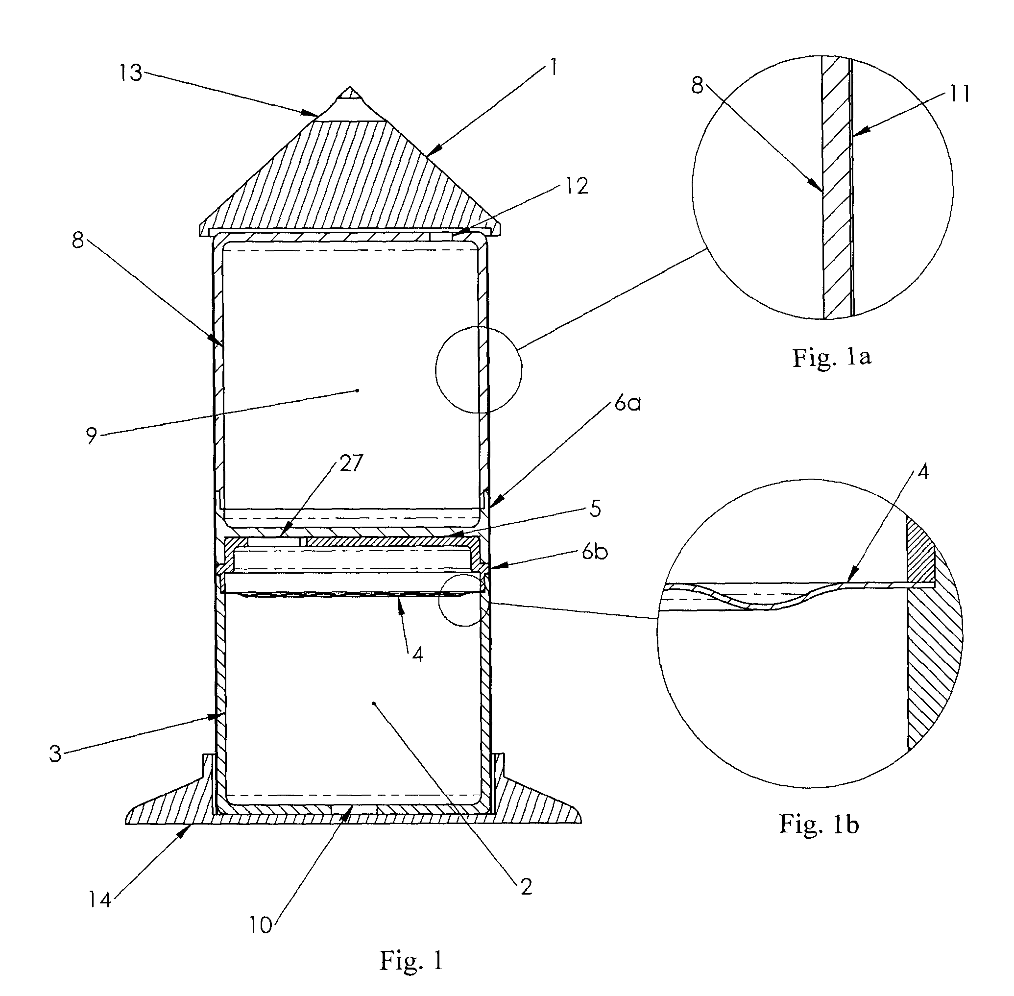
[0009]Consistent with the foregoing, an apparatus for delivering a beneficial agent is disclosed in one embodiment of the invention as including a water chamber. A water-transporting membrane is provided to communicate with the water chamber. An extraction chamber receives water through the water-transporting membrane, expanding the extraction chamber. A dispensing chamber, containing a beneficial agent, is configured to contract upon expanding the extraction chamber. This causes the dispensing chamber to expel the beneficial agent in some cases to a disseminating feature which may be related to evaporating the liquid through a wicking emanator. In certain embodiments, a rate adjustment mechanism may control the rate that water is received through the water-transporting membrane, thereby controlling the rate the beneficial agent is expelled. The water chamber may be designed in an open fashion where the user can fill by pouring water into it, or the chamber may be enclosed to prevent water from spilling. If the water chamber is enclosed, the volume preferably is either variable through a flexible member or it may be variable by having a piston member. Alternatively the water chamber may be vented to prevent a partial vacuum from forming in the water chamber during discharge. The vent may have a hydrophobic microporous plug or membrane to prevent spillage.
[0010]The water transporting membrane in this invention is different from the prior art. A membrane feature desired is a structure that repels osmagent constituents but is also water permeable. An example of a membrane that has such a structure is an ion exchange membrane. The ion exchange membrane may have varying backbone structure and varying functional groups of a particular polarity. For example, the backbone structure may be fluoropolymer based or styrene divinyl benzene based. The membranes may also have a backing material made from a material such as poly vinyl chloride to increase burst strength. The functional groups may be positively charged like a quaternary ammonia group or negatively charged like a sulfonate group. If the functional group is positively charged, then the membrane is classified as an anionic exchange membrane and conversely if the functional group is negatively charged then the membrane is considered a cation exchange membrane. One advantage of using such membranes is that they are water permeable but have a structure that slows down diffusion of salts or polar molecules. Reducing the diffusion of the osmagent is advantageous where the water in the water chamber is not continuously refreshed because the driving force for osmosis is reduced when osmagent diffuses into the water chamber and rate decreases. Examples of ion exchange membranes are Nafion by Dupont, and several membranes by ASTOM Corporation such as Neosepta CMX, AMX, CIMS, CMB, AHA, ACM, ACS, AFN and AFX. Other ion exchange membrane manufacturers and brands include Selemion by Asahi Glass. In particular, Neosepta CMB has been found to work very well, allowing good water flux but very little salt diffusion. Using this particular membrane, with ammonium phosphate dibasic as osmagent, steady delivery rates were obtained with a non-refreshed water compartment.
[0013]The delivery rate of the device may be adjusted by including a feature which masks part of the membrane and can be adjusted by increasing or decreasing the exposure of the membrane to the water.
[0015]In selected embodiments, the extraction chamber and the dispensing chamber are separated by a piston. In other embodiments, the extraction chamber and the dispensing chamber are separated by a flexible diaphragm. Where a flexible diaphragm is used, in selected embodiments, the flexible diaphragm may include several layers to prevent or reduce the diffusion of water through the diaphragm. In certain embodiments, a separator material, such as air or another gas or mixture of gases may be introduced between the layers to further prevent the water diffusion. In other embodiments, the flexible diaphragm may be coated with a water-impermeable material, such as metal, to prevent or reduce diffusion.

Problems solved by technology

A disadvantage of this approach is that water vapor pressure is very temperature dependant.
The vapor pressure at 10 C is 56% lower than at 23 C and at 44 C the vapor pressure is 326% that of 23 C. Thus temperature variations will have a very large impact on the dispense rate with this type of system which is very undesirable in most cases.
This significantly reduces the temperature sensitivity of the osmosis since the concentration of water is substantially unchanged over a temperature range as opposed to widely varying water vapor pressure.
A disadvantage of these membranes is that while they are substantially semipermeable, they still have permeability to many potential osmagents.
While the diffusion of osmagent is small, the effect over time can be very large when the volume of water contained is near the same amount of liquid to be dispensed and especially if the time scale of delivery is long.
The prior art does not teach how to obtain steady fluxes of water through a semipermeable membrane where osmagent is on one side and a non continuously refreshed water source is opposite and where variation in rate due to changes in temperature are minimal.

Method used


Image

  • Apparatus and method for delivering beneficial liquids at steady rate
  • Apparatus and method for delivering beneficial liquids at steady rate
  • Apparatus and method for delivering beneficial liquids at steady rate

Examples


Embodiment Construction

[0030]The invention has been developed in response to the present state of the art and, in particular, in response to the problems and needs in the art that have not yet been fully solved by currently available devices for delivering liquid beneficial agents such as fragrances, de-odorizers, sanitizers, pesticides and pest repellants. Such devices either suffer from a decline in delivery performance over time to the point that the benefits are no longer rendered or when the devices are active and have acceptable performance, the devices are complex in nature which results in high cost. Accordingly, the invention has been developed to provide novel apparatus and methods for delivering liquid beneficial agents to target areas in a controlled and predictable manner and where impact of temperature variation is minimal. The features and advantages of the invention will become more fully apparent from the following description and appended claims and their equivalents, and also any subseq...


PUM


Abstract

An apparatus for delivering a beneficial agent is disclosed in one embodiment of the invention as including a water collection chamber. A water-transporting membrane is provided to communicate with the water collection chamber. An extraction chamber receives water through the water-transporting membrane, expanding the extraction chamber. A dispensing chamber, containing a beneficial agent, is configured to contract upon expanding the extraction chamber. This causes the dispensing chamber to expel the beneficial agent through a subterranean delivery channel, such as a rigid hollow spike. In certain embodiments, a rate adjustment mechanism may control the rate that water is received through the water-transporting membrane, thereby controlling the rate the beneficial agent is expelled. The water-transporting membrane has features that repel osmagent from passing through to the water collection chamber. The apparatus features steady rate performance without refreshing the water chamber and low temperature sensitivity.

Description

CROSS-REFERENCE TO RELATED APPLICATION[0001]This application is a continuation-in-part of U.S. patent application Ser. No. 12 / 100,982 filed Apr. 10, 2008 entitled Apparatus and Method For Delivery Beneficial Agents to Subterranean Locations, which is hereby incorporated by reference. This application also claims priority to U.S. Provisional Patent No. 61 / 092,538 filed on Aug. 28, 2008 and entitled Apparatus and Methods For Delivering Beneficial Liquids at Steady Rate, and which is also hereby incorporated by reference.BACKGROUND[0002]This invention relates to apparatus and methods for delivering beneficial liquids such as fragrances, deodorizers, sanitizers, pesticides and pest repellants at a steady rate for extended time periods using an osmotic pump and where the source of water for the osmosis typically is not continuously refreshed.[0003]What are needed are apparatus and methods for delivering liquid beneficial agents, such as fragrances, de-odorizers, sanitizers, pesticides an...

Claims


Application Information

Patent Timeline
IPC IPC(8): A61M5/142
CPCA61L9/12A01M1/2044Y10T137/2931
Inventor GORDON, JOHN HOWARDJOSHI, ASHOK V.WOLD, TRUMANBHAVARAJU, SAI
Owner MICROLIN
Why Eureka
Eureka Blog
Learn More