Microfluidic Synthesis of Organic Nanoparticles
a technology of organic nanoparticles and microfluidic synthesis, which is applied in the field of microfluidic synthesis of organic nanoparticles, can solve the problems of not being able to achieve the economic feasibility of rapid production and screening of particle libraries, and the current methods of manufacturing particles for drug delivery do not allow for controlled synthesis of particles with engineered properties, so as to achieve the effect of reducing labor and time consumption
- Summary
- Abstract
- Description
- Claims
- Application Information
AI Technical Summary
Benefits of technology
Problems solved by technology
Method used
Image
Examples
example 1
Fabrication of a Microfluidic Device
[0244]Two methods were employed in order to fabricate microfluidic devices. In the first method, a photocurable epoxy (SU-8, Microchem Inc.) was spun onto a glass (pyrex) wafer to a thickness of 40 μm-100 μm. After standard lithography procedures, microchannels were obtained on the wafer. Holes were drilled in the wafer and another wafer was bonded to the first wafer to form enclosed microchannels. Connections were made from syringes to the device using tubing and sealing the tubing to the device using epoxy. This device had microchannels made of glass and SU-8.
[0245]In the second method, standard procedures of soft lithography were used to make the devices from polydimethylsiloxane (PDMS). The device was obtained by first making a master mold using SU-8 lithography followed by silane treatment. PDMS pre-polymer and curing agent (Sylgard 184, Dow Corning) were mixed in the ratio prescribed by the manufacturer, poured on the master mold and cured. ...
example 2
Synthesis of PLGA-PEG Nanoparticles in a Microfluidic Device
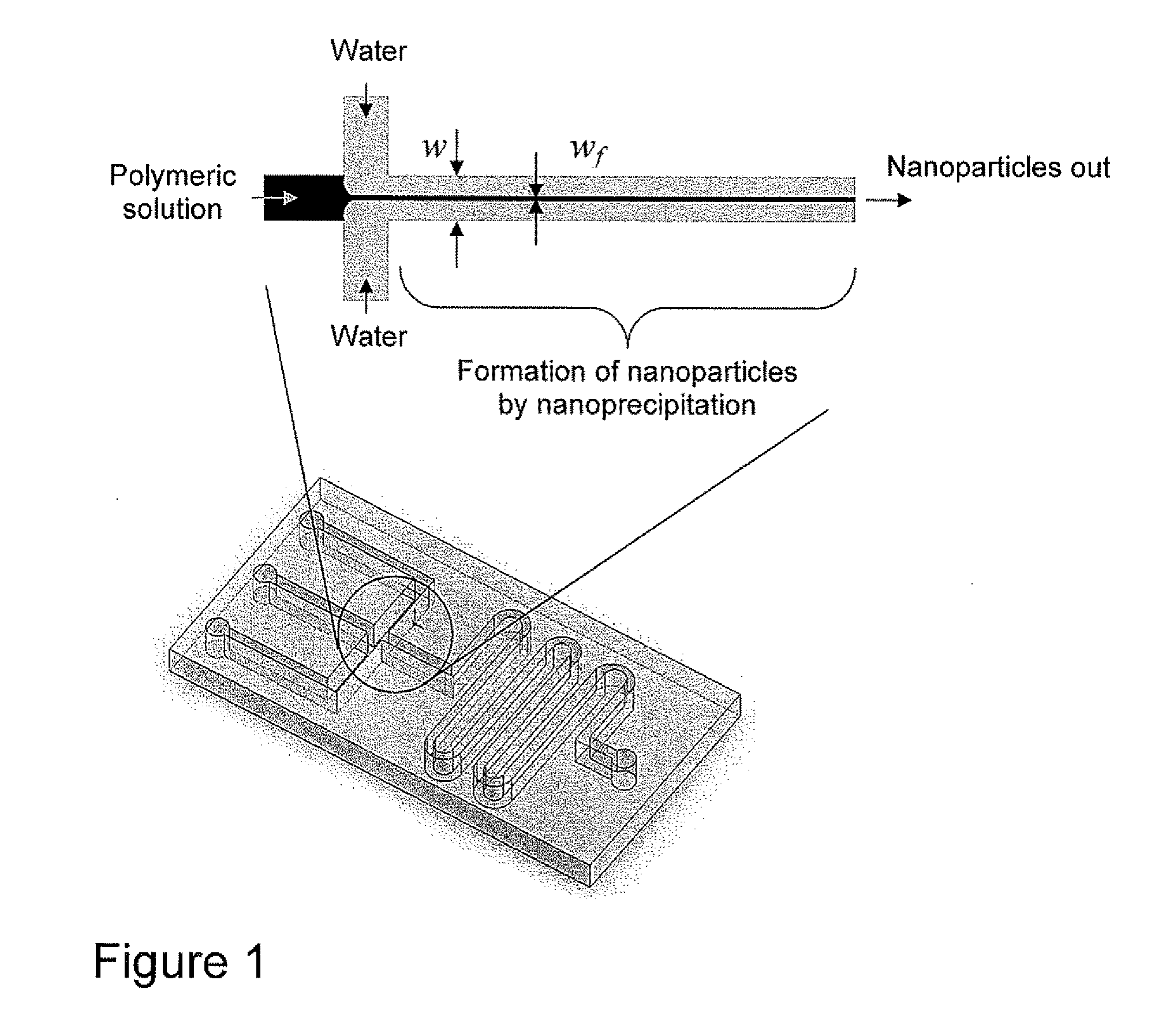
[0246]PLGA-PEG nanoparticles were synthesized by nanoprecipitation using the devices described in Example 1. 50 mg / ml PLGA-PEG solution in acetonitrile was injected in the polymeric stream using a syringe pump at varying flow rates. The outer two streams were water. Nanoparticles that were formed in the microfluidic device were collected and characterized in a Zeta-PALS system. As a control, the same amount of nanoparticles was formed by adding the same amount of polymeric solution into the same quantity of water by hand using a pipette. FIG. 8 shows nanoparticle distributions for nanoparticles formed using the microfluidic device and the nanoparticles synthesized manually. It is seen that the nanoparticles synthesized using the microfluidic device are highly monodisperse in size as compared to those synthesized manually. Without wishing to be bound by any one theory, this may be due to the highly controlled nanoprecipitati...
example 3
Effect of Flow Ratio on Nanoparticle Size
[0247]The term “flow ratio” refers to the polymeric solution flow rate as a fraction of water flow rate. Increasing the flow ratio results in increase of mixing time and increase of the size of produced particles. Three polymeric solutions—50 mg / mL PLGA-PEG in acetonitrile, 20 mg / mL PLGA-PEG in acetonitrile, and a mixture of 40 mg / mL PLGA-PEG and 10 mg / mL PLGA (20% PLGA)—exhibit the same trend (FIG. 9). PLGA-PEG copolymer consisted of ˜74 kDa PLGA block and ˜3.4 kDa PEG block, while PLGA was ˜74 kDa. Water flow rate was maintained at 10 μl / min.
[0248]Nanoparticles that were prepared by addition of 3 μl polymeric solution to 60 μl using a pipette (Bulk) are seen to be consistently larger than those prepared using microfluidics. However, this effect is dramatically increased for 20% PLGA, where the nanoparticles prepared using bulk method are nearly three times larger than those prepared using microfluidics (FIG. 9). Volume-averaged particle siz...
PUM
| Property | Measurement | Unit |
|---|---|---|
| height | aaaaa | aaaaa |
| height | aaaaa | aaaaa |
| height | aaaaa | aaaaa |
Abstract
Description
Claims
Application Information
 - R&D
- Intellectual Property
- Life Sciences
- Materials
- Tech Scout
- Unparalleled Data Quality
- Higher Quality Content
- 60% Fewer Hallucinations
Browse by: Latest US Patents, China's latest patents, Technical Efficacy Thesaurus, Application Domain, Technology Topic, Popular Technical Reports.
© 2025 PatSnap. All rights reserved.Legal|Privacy policy|Modern Slavery Act Transparency Statement|Sitemap|About US| Contact US: help@patsnap.com


