Photoelectric conversion device, multichip module type image sensor, contact image sensor, and image scanner
a conversion device and image sensor technology, applied in the field of photoelectric conversion devices, can solve the problems of reducing sensitivity, affecting the image quality of color images, and generating differences in sensitivity in each pixel column, so as to suppress the decrease in sensitivity, the difference in capacitance, and the effect of sensitivity differen
- Summary
- Abstract
- Description
- Claims
- Application Information
AI Technical Summary
Benefits of technology
Problems solved by technology
Method used
Image
Examples
first embodiment
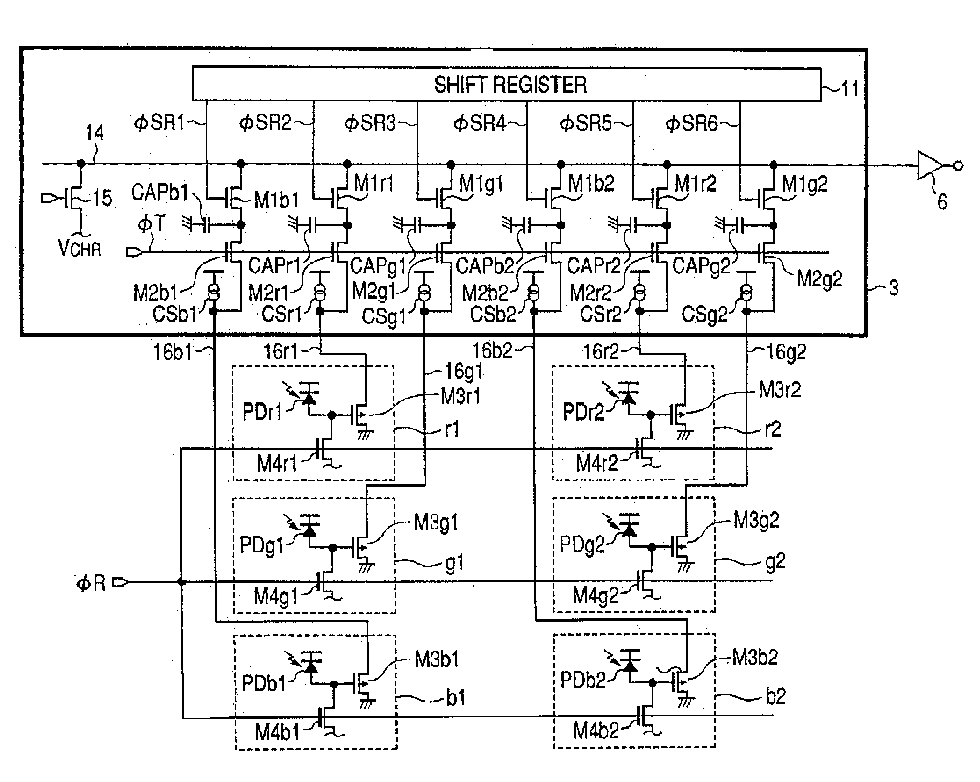
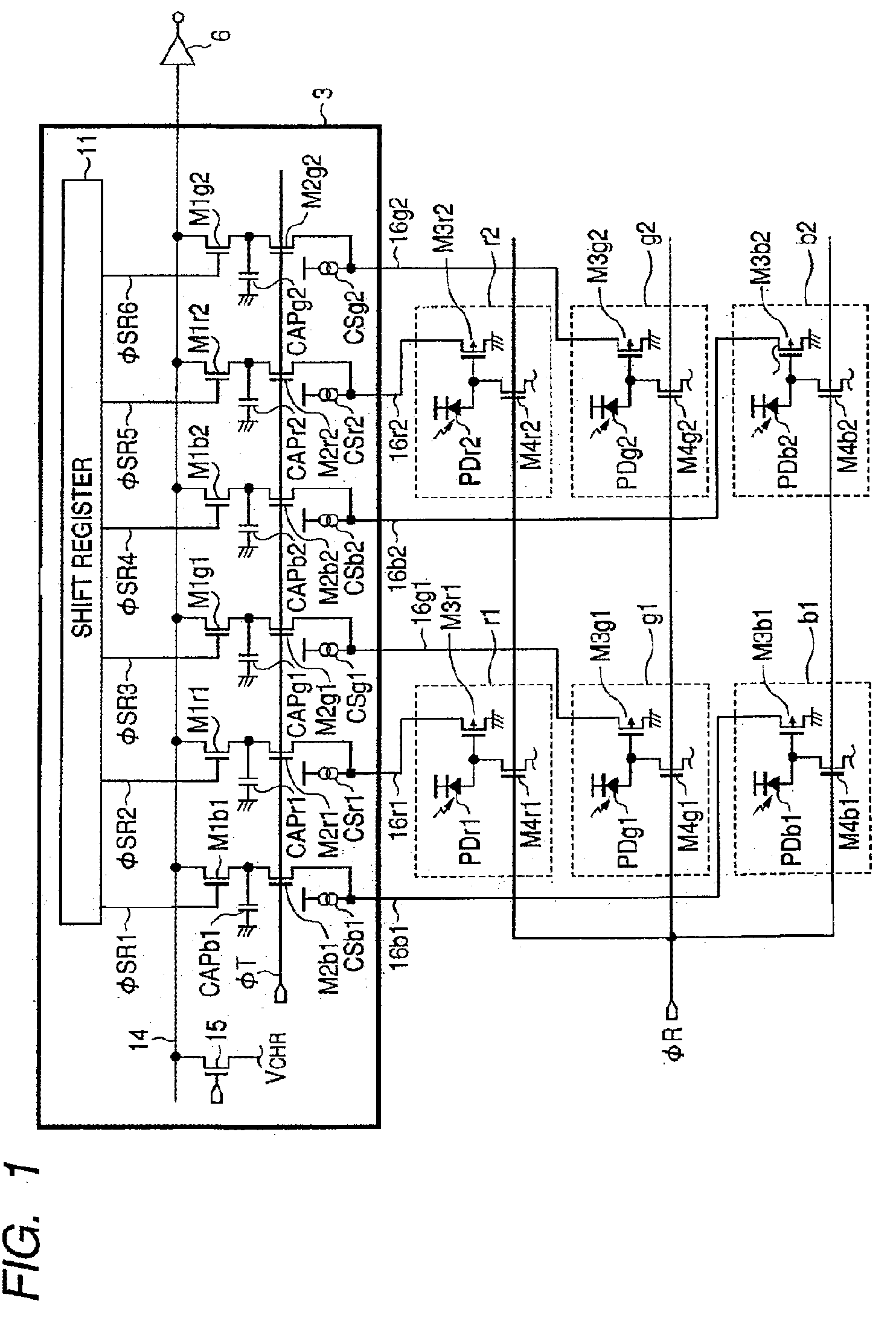
[0047]FIG. 1 shows a configuration of a light receiving element according to a first embodiment of the invention. FIG. 1 shows an equivalent circuit corresponding to the readout circuit block 3 and light receiving element array 4 (only two-pixel-by-three-column light receiving element (three pixel columns) is shown) shown in FIG. 6. The equivalent circuit of the color image sensor in the first embodiment is similar to the equivalent circuit diagram shown in FIG. 6, and the configuration and the operation are already described, so that the description will be not repeated. In FIG. 1, the component similar to that of FIG. 8 is designated by the same reference numeral or sign.
[0048]Referring to FIG. 1, the light receiving elements (constituting the pixel) r1 to b2 include the photodiode PDr1 to PDb2 which are of the photoelectric conversion element, the MOS source follower input transistors M3r1 to M3b2, and the reset switches (reset transistors) M4r1 to M4b2 which are of the means for...
second embodiment
[0058]FIG. 3 shows a configuration of a light receiving element according to a second embodiment of the invention. FIG. 3 shows an equivalent circuit corresponding to the readout circuit block 3 and light receiving element array 4 (only two-pixel-by-three-column light receiving element is shown) shown in FIG. 6. The equivalent circuit of the color image sensor in the second embodiment is similar to the equivalent circuit diagram shown in FIG. 6, and the configuration and the operation are already described, so that the description will be not repeated. In FIG. 1, the component similar to that of FIG. 8 is designated by the same reference numeral or sign.
[0059]In the second embodiment, the invention is applied to the photoelectric conversion device having a depletion transfer type pixel. In FIG. 3, second signal transfer switches M6r1 to M6b2 are collectively turned on, and the signal charges are collectively and completely depletion-transferred from the photodiodes PDr1 to PDb2 to t...
third embodiment
[0069]FIG. 5 shows a photoelectric conversion device according to a third embodiment of the invention. The six-column light receiving element is configured so as to output the light signals while the six-column light receiving element is divided into each three columns of upper and lower portions. The reference numeral 1101 denotes a light receiving element, the reference numerals 3-1 and 3-2 designate a readout circuit block, and the reference numeral 6 denotes a signal output amplifier. The three-column light receiving element column is described in the first and second embodiments. However, as the number of pixel columns is increased as shown in FIG. 5, the number of readout wirings 16 running between the light receiving elements is increased. Therefore, it is necessary to secure the wiring area by decreasing an aperture area of the photodiode, which decreases the sensitivity. However, in the third embodiment, even if the number of light receiving element columns doubles the firs...
PUM
 Abstract
Description
Claims
Application Information
 - R&D
- Intellectual Property
- Life Sciences
- Materials
- Tech Scout
- Unparalleled Data Quality
- Higher Quality Content
- 60% Fewer Hallucinations
Browse by: Latest US Patents, China's latest patents, Technical Efficacy Thesaurus, Application Domain, Technology Topic, Popular Technical Reports.
© 2025 PatSnap. All rights reserved.Legal|Privacy policy|Modern Slavery Act Transparency Statement|Sitemap|About US| Contact US: help@patsnap.com


