Electric motor

a technology of electric motors and motors, applied in the direction of synchronous motor starters, dc motor stoppers, ac motor stoppers, etc., can solve the problems that the fan being driven by such a motor cannot reach high rotation speeds, and the short-circuit braking function is automatically activated, so as to facilitate the startup

Active Publication Date: 2009-12-24
EBM PAPST ST GEORGEN & -
View PDF10 Cites 15 Cited by
  • Summary
  • Abstract
  • Description
  • Claims
  • Application Information

AI Technical Summary

Benefits of technology

[0005]According to the present invention, this object is achieved by an electric motor in which its program-controlled calculation device, in the event of a power outage, promptly ceases to supply signals to the semiconductor switches, and a charge stored on an internal energy storage device is used to short-circuit the stator windings and promptly decelerate the motor rotor and any fan blades attached thereto. When such a motor is switched off, the energy that serves to supply the calculation device is used up practically instantaneously, so that the calculation device can no longer supply signals to the Metal Oxide Semiconductor Field Effect Transistors (MOSFETs) controlling the stator winding currents, with the result that a short-circuit braking function is automatically activated.
[0006]The following is highly advantageous in this context: when such a motor, in a shut-off state, is driven by air flows that cause the rotor of a fan to rotate, the motor acts as a generator and generates a voltage at the link circuit, which voltage charges the storage device provided there. Because the program-controlled calculation device continues to be deactivated under these conditions, the short-circuit braking function is automatically switched on in this case as well, so that, for example, a fan being driven by such a motor cannot reach high rotation speeds. This is advantageous, in particular, when such a fan is driven in the “wrong” rotation direction by the air flow. In an experiment, for example, a fan was driven by such an air flow at 3500 rpm in the wrong direction when the short-circuit braking function was not activated; and with the short-circuit braking function activated, that rotation speed was reduced to 500 rpm, with no use of external electrical energy.
[0007]In such a case, this facilitates startup in the correct direction, since the motor needs first to be decelerated only from 500 (rather than 3500!) rpm to zero rpm, and then accelerated to, for example, the rated rotation speed of 6000 rpm.
[0008]What is obtained is therefore a fan that electrically brakes itself without an external supply of electrical energy, or that prevents uncontrollable air flow from producing high rotation speeds that might, for example, injure a maintenance engineer.

Problems solved by technology

When such a motor is switched off, the energy that serves to supply the calculation device is used up practically instantaneously, so that the calculation device can no longer supply signals to the Metal Oxide Semiconductor Field Effect Transistors (MOSFETs) controlling the stator winding currents, with the result that a short-circuit braking function is automatically activated.
Because the program-controlled calculation device continues to be deactivated under these conditions, the short-circuit braking function is automatically switched on in this case as well, so that, for example, a fan being driven by such a motor cannot reach high rotation speeds.

Method used


Image

  • Electric motor
  • Electric motor
  • Electric motor

Examples


Embodiment Construction

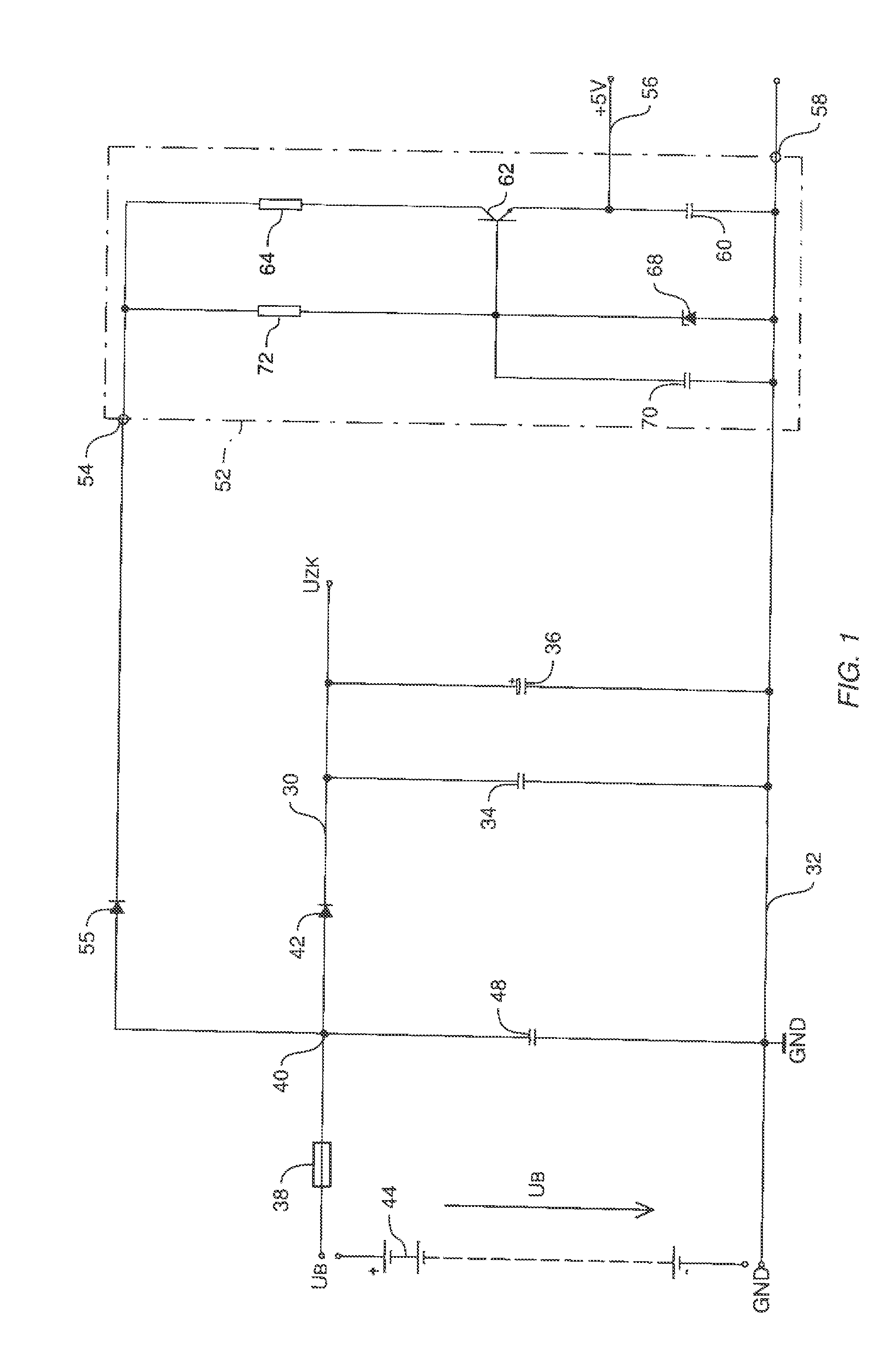
[0015]FIG. 1 shows positive branch 30 of a DC link circuit, a voltage UZK being present between said branch and ground 32, during operation. In the case of a fan, this voltage is often in a range between 8 and 100 VDC, but can also be higher or lower.

[0016]Some motors can be operated in a relatively wide voltage range, e.g. between 20 V and 80 VDC. Located between positive branch 30 and ground 32 is a capacitor 34 for filtering out high-frequency interference, and a so-called “link circuit” capacitor 36 having a higher capacitance, usually an electrolytic capacitor.

[0017]Lead 30 can be connected via a fuse 38, a node 40, and a diode 42 to an external operating voltage UB, depicted here symbolically as battery 44, e.g. as the local battery of a telephone switching center. Located between node 40 and ground 32 is a capacitor 48 that serves to filter out interference.

[0018]FIG. 1 also shows a circuit 52 whose positive input 54 is connected via a diode 55 to node 40, and that generates ...


PUM


Abstract

An electric motor has a DC link circuit (30, 32), a permanent-magnet rotor (104), and a control circuit having a full bridge (114). A program-controlled calculation arrangement (80) is configured to supply the semiconductor switches of a first bridge half with a PWM signal (136, 136′) and to supply the semiconductor switches (118, 122) of the second bridge half with a commutation signal (O1, O2; 150, 150′). An energy storage device (170) is provided which, during normal operation of the motor (102), is chargeable from the DC link circuit (30, 32) and serves, upon cessation of the signals from the calculation arrangement (80), to make the semiconductor switches (118, 122) of the other bridge half conductive, and thereby to short-circuit the stator winding arrangement (106) through those semiconductor switches (118, 122) in order to decelerate the permanent-magnet rotor (104) and to thereby minimize risk of human injury.

Description

CROSS-REFERENCE TO RELATED APPLICATION(S)[0001]This application claims priority from our German application DE 20 2008 008 563.2, filed 19 Jun. 2008, the entire content of which is hereby incorporated by reference.FIELD OF THE INVENTION[0002]The present invention relates to an electronically commutated motor (ECM), as used principally to drive fans.BACKGROUND[0003]Such fans are used, among other purposes, to cool electrical cabinets. When such an electrical cabinet is opened, the fans are automatically switched off, but they continue to rotate for a while, and the risk therefore exists, that someone may bring his or her hand into contact with the sharp rotating blades on the rotor of such a fan. It is therefore important that, as soon as such a fan becomes currentless (for whatever reason), it is automatically decelerated very quickly, in order to minimize the risk of human injury.SUMMARY OF THE INVENTION[0004]It is therefore an object of the invention to make available a novel elec...

Claims


Application Information

Patent Timeline
Patent Type & Authority Applications(United States)
IPC IPC(8): H02P3/12
CPCH02P6/008H02P6/002H02P6/28H02P6/26
Inventor KARWATH, ARNONOCITA, ELVIS
Owner EBM PAPST ST GEORGEN & -
Why Eureka
Try Eureka