
Method of delivering a thermoplastic and/or crosslinking resin to a composite laminate structure

a technology of thermoplastic and crosslinking resin, which is applied in the direction of packaging foodstuffs, packaged goods types, other domestic articles, etc., can solve the problems of low fiber volume and concomitantly higher than desired finished thickness per ply, ply is thicker than desired, and resin lacking fiber reinforcement has poor strength

Inactive Publication Date: 2009-12-17
KEUCHEL KENNETH HERBERT
View PDF51 Cites 44 Cited by
  • Summary
  • Abstract
  • Description
  • Claims
  • Application Information

AI Technical Summary

Benefits of technology

[0018]The present invention provides a process for producing a prepreg of reinforcing fibers, the process comprising the steps of: a) providing a reinforcing fiber bundle layer wherein such bundle contains a thermoplastic and/or crosslinking resin within the fiber bundle; b) pr

Problems solved by technology

A common problem with these structures and panels has been lower than desired fiber volumes and concomitantly higher than desired finished thickness per ply for aerospace use.
In traditional resin infusion failure to optimize the thickness often means that each ply is thicker than necessary.
Resin lacking fiber reinforcement has poor strength, so uncontrolled plies in a laminate can form a pattern of high strength areas sandwiched between lower strength areas.
More plies translate to more material and more labor, making already expensive parts even more expensive.
It also translates to more weight, reducing overall performance of the aerospace system in which the composites are used.
The prepreg materials typically are expensive (especially those using high modulus carbon fiber).
The raw prepreg materials have limited shelf lives because the resins that impregnate the fibers may continue to react (“advance”) at ambient temperature.
Advance of the resin adversely affects the properties of the resulting composite.
However, since the thermoplastic resin fibers are disposed as short fibers, the prepreg becomes bulky and has such a problem with drapability that it cannot be easily shaped, depending on the shape of the mold.
Furthermore, since a water jet is used, it can cause the reinforcing fibers to be broken or become curved, and there arises such a problem that the molded article may have inferior surface appearance, mechanical properties, etc.
As mentioned, the prepregs have a limited shelf life.
Reaction of the monomer reactants of the polymer (i.e., its advancing) prior to the intended cure cycle adversely impacts the quality of the final composite because it will be unsuitable for subsequent processing.
Liquid molding techniques such as transfer molding, resin film infusion, resin transfer molding, and structural reaction injection molding (SRIM) typically require expensive matched metal dies and high tonnage presses or autoclaves.
Parts produced with these processes are generally limited in size and geometry.
The conventional liquid molding resins do not provide the necessary properties for many applications for the composites.
When manufacturing a thermoplastic or crosslinking resin impregnated composite laminate structure, the delivery of the resin system is sometimes difficult because of the high viscosity of such thermoplastic or even some crosslinking resins.
When infusing the resin from the outside of the bundle of high modulus fibers, such as carbon fibers or Kevlar® polyphenylene terephthalamide fibers, it can be difficult to substantially completely coat the resin (“wet out”) on all of the high modulus fibers within the yarn bundles.
Thermoplastic compositions are more difficult to impregnate into the reinforcing material because of their comparatively higher viscosities.
These methods have suffered from serious drawbacks.
In the case of using solvent to reduce viscosity, the solvent must be driven off after the impregnation step, resulting in an additional step in the process as well as unwanted volatile emissions.
In the case of heating the thermoplastic matrix in order to reduce its viscosity, the dwell time of the resin in the heated zone may result in degradation of the resin, with attendant decrease in the desired mechanical properties.
Outgassing during consolidation often results in voids within the composite that can cause micro-cracking or premature delaminating that may adversely affect mechanical properties.
Outgassing during coating steps tends to cause pin holing or popping in the substrate or coating, resulting in an undesirably rough and blemished surface or finish.

Method used


Image

  • Method of delivering a thermoplastic and/or crosslinking resin to a composite laminate structure
  • Method of delivering a thermoplastic and/or crosslinking resin to a composite laminate structure

Examples


example

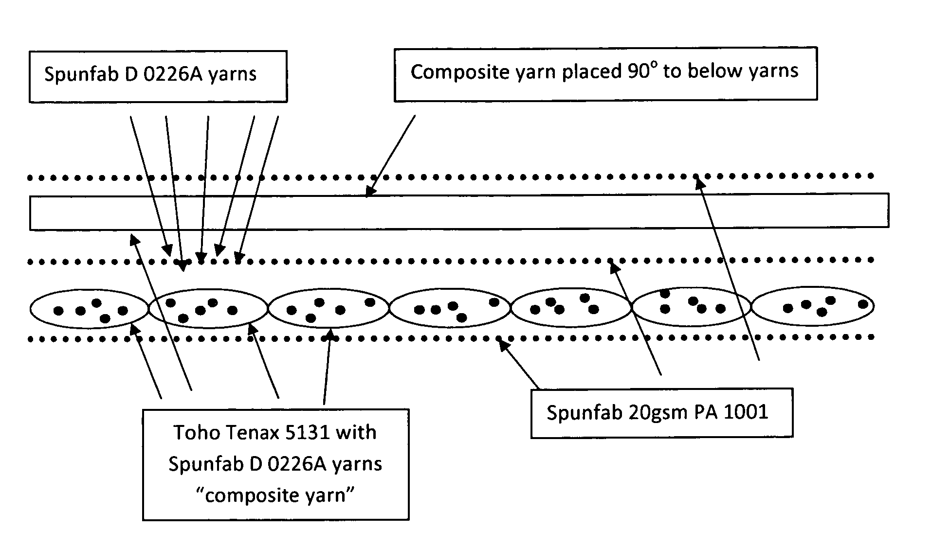
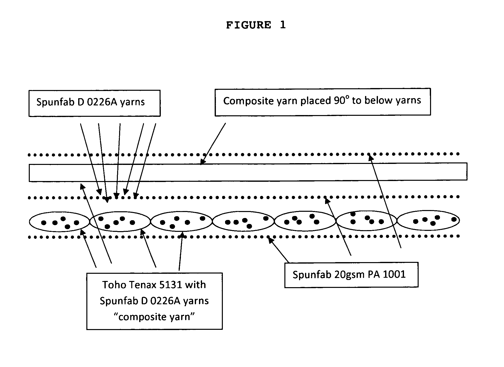
[0046]A spool of Toho TENAX carbon yarn type HTA-5131 (available from Toho Tenax America, Inc.) at 200 tex is unspooled and plied with 3 spools of Spunfab D 0226A thermoplastic yarn (available from Spunfab Ltd.) at 50 denier per spool. The resultant yarns will hereafter he referred to as “composite yarn”. The composite yarn is then wound onto a final spool.

[0047]The a first layer of the resultant composite yarn is laid uniaxially parallel on top of a first layer of Spunfab 20 gsm PA 1001 non-woven web (available from Spunfab Ltd.). A second layer of 20 gsm Spunfab PA 1001 non-woven web is then placed on top of the first layer of composite yarn. A second layer of uniaxially laid parallel composite yarn is then placed at 90° to the first layer of composite yarn. Then a third layer of 20 gsm Spunfab PA 1001 non-woven web is placed on top of the second layer of composite yarn.

[0048]Release paper is placed on the top and bottom of the above sandwiched composite layers and the sandwiched ...


PUM

PropertyMeasurementUnit
Percent by massaaaaaaaaaa
Fractionaaaaaaaaaa

Abstract

The present invention provides a process for producing a prepreg of high modulus reinforcing fibers, the process comprising the steps of: a) providing a reinforcing fiber bundle layer wherein such bundle contains a thermoplastic and / or crosslinking resin within the fiber bundle; b) providing a layer of a thermoplastic and / or crosslinking material layer on at least one side of the high modulus fiber layer of step a); c) compressing the layers from step b) under an appropriate amount of heat and pressure, and thereby producing a prepreg of high modulus reinforcing fibers.

Description

CROSS REFERENCE TO RELATED APPLICATIONS[0001]This application claims priority upon both U.S. Provisional Applications Ser. No. 61 / 131,773, filed Jun. 12, 2008 and U.S. Provisional Application Ser. No. 61 / 209,594, filed Mar. 9, 2009. These applications are hereby incorporated by reference in their entirety for all of their teachings.BACKGROUND OF THE INVENTION[0002]The marine, automotive, trucking, rail, aerospace, defense, recreation, chemical, infrastructure, and other industries look to composite materials to take advantage of their unique properties, especially being corrosion-free or corrosion-resistant and having a high strength-to-weight ratio. Composites are also resistant to fatigue and chemical attack. They offer high strength and stiffness potential in lightweight components. There is a need, however, to develop composite manufacturing processes, especially with reduced cycle times, which dramatically reduce the cost of composites, especially large structures, while retain...

Claims


Application Information

Patent Timeline
IPC IPC(8): B29C70/50
CPCB29C70/50B29B15/12B32B5/28B32B5/022B32B5/08B32B5/26B32B2250/20B32B2260/021B32B2260/046B32B2262/02B32B2262/14B32B2439/00B32B2601/00B32B2605/00B32B2605/18
Inventor KEUCHEL, KENNETH HERBERT
Owner KEUCHEL KENNETH HERBERT
Learn More