
Fluid bearing device

a technology of bearings and bearing sleeves, which is applied in the direction of bearings, shafts and bearings, rotary bearings, etc., can solve the problems of high moment rigidity, difficult to accurately perform positioning fixation of this kind, and difficult to manage the clearance of thrust bearings with high accuracy. , the effect of high accuracy

Inactive Publication Date: 2009-12-03
NTN CORP
View PDF14 Cites 17 Cited by
  • Summary
  • Abstract
  • Description
  • Claims
  • Application Information

AI Technical Summary

Benefits of technology

The present invention relates to a fluid bearing device used in various equipment such as information equipment and small motors. The invention aims to address the issue of position accuracy and assembly accuracy of bearing sleeves with respect to a housing, as well as the need for increased bearing rigidity. The invention proposes a structure in which two bearing sleeves are arranged in the axial direction with radial bearing portions formed in the radial bearing clearances between the bearing sleeves and the shaft member. This structure allows for increased bearing rigidity without requiring enlarged bearing sleeves and ensures uniform density of the bearing sleeves. The technical effects of the invention include improved position accuracy and assembly accuracy of bearing sleeves with respect to the housing, as well as increased bearing rigidity.

Problems solved by technology

As described above, in the case of using the plurality of bearing sleeves, position accuracy (such as coaxiality) between the bearing sleeves and assembly accuracy of the bearing sleeves with respect to the housing are issues to be considered.
However, in the fluid bearing device having a structure including a spacer interposed between the bearing sleeves, it is not easy to accurately perform the positioning fixation of this kind.
In a case where a total sum of dimensional tolerances of the above-mentioned components is equal to or larger than requisite widths of the thrust bearing clearances, it is difficult to manage the thrust bearing clearances with high accuracy.
However, with this structure, along with enlargement of the bearing span, it is necessary to elongate and enlarge the bearing sleeves.
When the bearing sleeves are elongated and enlarged, it is difficult to ensure finishing accuracy of the bearing sleeves.
In particular, when the bearing sleeves are made of sintered metal, uniform density thereof cannot be easily obtained at a time of powder compaction thereof, so there is a risk in that desired bearing performance cannot be exerted.
When a width of the axial clearance is smaller than a width of each of the adhesion clearances, the adhesive charged into the adhesion clearances at the time of adhesive fixation is led into the radial clearances by a capillary force, and there is a risk in that the adhesive enters and is solidified in an inner diameter side of the bearing sleeves (radial bearing clearances), thereby affecting the bearing performance.
Further, depending on an assembling procedure for the bearing sleeves or a charging method for the adhesive, the same problems are induced in some cases.

Method used


Image

  • Fluid bearing device
  • Fluid bearing device
  • Fluid bearing device

Examples


first embodiment

[0033]First, a description is made of the present invention with reference to FIGS. 1 to 5.

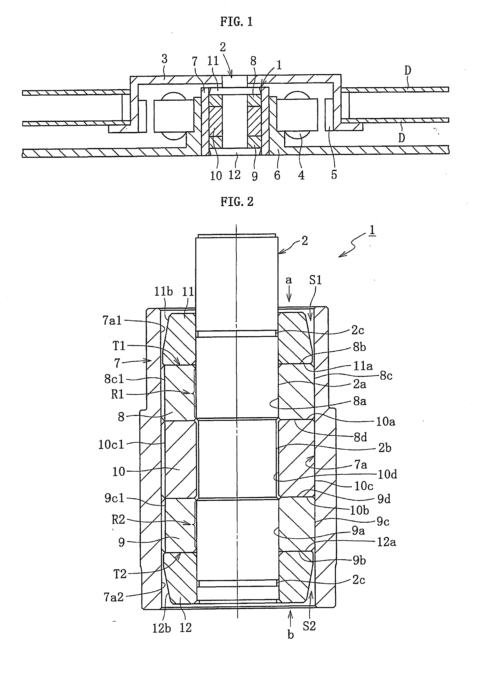
[0034]FIG. 1 conceptually illustrates a structural example of a spindle motor for information equipment according to a first embodiment of the present invention, in which a fluid bearing device (dynamic pressure bearing device) 1 is incorporated. The spindle motor is used for a disk drive device such as an HDD. The spindle motor includes a fluid bearing device 1 for rotatably supporting a shaft member 2, a hub 3 fixed to the shaft member 2, a stator coil 4 and a rotor magnet 5 opposed to each other through intermediation of a radial gap, for example, and a bracket 6. The stator coil 4 is mounted to an outer periphery of the bracket 6. The rotor magnet 5 is mounted to an inner periphery of the hub 3. The fluid bearing device 1 is fixed to an inner periphery of the bracket 6. The hub 3 holds one or a plurality of (two in FIG. 1) disks D serving as information recording media. In the spindle moto...

third embodiment

[0085]FIG. 7 is a diagram conceptually illustrating a construction example of an information apparatus spindle motor into which a fluid bearing device (fluid dynamic pressure bearing device) 31 according to the present invention is incorporated. The spindle motor is used in a disk drive, such as an HDD, and is equipped with: the fluid bearing device 31 for rotatably supporting a shaft member 32 in a non-contact manner; a rotor (disk hub) 33 mounted to the shaft member 32; and a stator coil 34 and a rotor magnet 35 opposed to each other through the intermediation of, for example, a radial gap. The stator coil 34 is mounted to an outer periphery of a bracket 36, and the rotor magnet 35 is mounted to an inner periphery of the disk hub 33. A housing 37 of the fluid bearing device 31 is mounted to the inner periphery of the bracket 36. One or a plurality of disks D such as magnetic disks are retained by the disk hub 33. When electricity is supplied to the stator coil 34, the rotor magnet...

second embodiment

[0125]FIG. 6 is a sectional view illustrating a fluid bearing device according to the present invention.

[0126]FIG. 7 is a sectional view illustrating a spindle motor in which a fluid bearing device according to a third embodiment of the present invention is incorporated.

[0127]FIG. 8 is a sectional view of the fluid bearing device according to the third embodiment of the present invention.

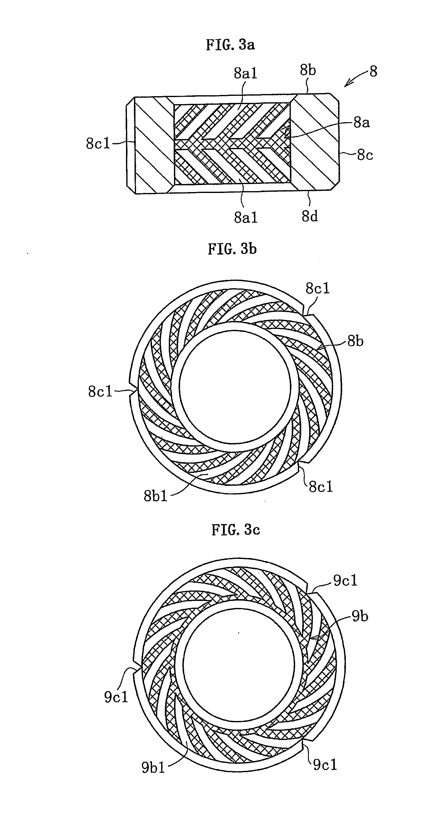
[0128]FIG. 9(a) is a view illustrating an upper end surface of a first bearing sleeve, FIG. 9(b) is a longitudinal sectional view of a bearing sleeve, and FIG. 9(c) is a view illustrating a lower end surface of a second bearing sleeve.

[0129]FIG. 10 is a longitudinal sectional view illustrating a bearing sleeve according to another mode of the present invention.


PUM


Abstract

[Problems] Provided is a fluid bearing device in which bearing sleeves are positioned and fixed with respect to a housing with high accuracy.[Solving Means] To an inner periphery of a housing (7), a first bearing sleeve (8) and a second bearing sleeve (9) are fixed while being spaced apart in an axial direction. Between the bearing sleeves (8) and (9), a spacer (10) made of a resin is disposed. An axial rigidity of the spacer (10) is smaller than those of the first bearing sleeve (8) and the second bearing sleeve (9). Accordingly, in a state where the first bearing sleeve (8) and the second bearing sleeve (9) are positioned and fixed with respect to the housing (7), the spacer (10) is largely compressed in an axial direction compared to the bearing sleeves (8) and (9).

Description

TECHNICAL FIELD[0001]The present invention relates to a fluid bearing device.BACKGROUND ART[0002]The fluid bearing device relatively rotatably supports a shaft member by a lubricating film of a fluid caused in a bearing clearance. Recently, by taking advantage of its excellent rotational accuracy, high-speed rotation property, quietness, and the like, the fluid bearing device is used, for example, as a bearing for a spindle motor mounted on information equipment including magnetic disk devices such as HDD and FDD, optical disk devices such as CD-ROM, CD-R / RW, and DVD-ROM / RAM, and magneto-optical disk devices such as MD and MO, and as a bearing for small motors such as a polygon scanner motor for a laser beam printer (LBP), a color wheel motor for a projector, or a fan motor.[0003]For example, as a fluid bearing device incorporated in the spindle motor for an HDD, there is known one having a structure in which both a radial bearing portion for supporting the shaft member in a radial ...

Claims


Application Information

Patent Timeline
Patent Type & Authority Applications(United States)
IPC IPC(8): F16C32/06
CPCF16C17/107F16C35/02F16C33/107F16C17/26F16C33/10F16C17/10F16C33/74
Inventor HORI, MASAHARUTODA, MASAAKI
Owner NTN CORP
Learn More