Disc rotor for disc brake

a disc brake and disc rotor technology, applied in the direction of braking discs, mechanical equipment, transportation and packaging, etc., can solve the problem of inverse proportional increase in pad pressure stress in the square of the disc thickness, and achieve the effect of reducing torque stress, large radius and relatively large torque stress in braking

Inactive Publication Date: 2009-12-03
HITACHI CHEM CO LTD
View PDF4 Cites 3 Cited by
  • Summary
  • Abstract
  • Description
  • Claims
  • Application Information

AI Technical Summary

Benefits of technology

[0017]According to the invention, since the inner peripheral corner of the vent hole, where torque stress in braking is relatively large, can have a larger radius while the vent hole height is constant, torque stress can be reduced.
[0018]Similarly, torque stress in braking can be reduced while the vent hole height is constant. In this case, even when the vent hole shape is changed, the width W of the beam part of the sliding part is the same as in the conventional structure, so an increase in pad pressure stress due to the change in the vent hole shape can be suppressed more effectively than with the above structure. In addition, since the radius of the inner peripheral corner of the disc rotor is larger than in the conventional shape, torque stress can be further reduced.

Problems solved by technology

For this reason, C / SiC disc rotors have a problem that the mechanical stress applied to them during braking may cause cracking.
In other words, a problem with the conventional vent hole shape as shown in FIGS. 7A and 7B is that when the vent hole height is increased to reduce torque stress (disc thickness is decreased), the pad pressure stress largely increases in inverse proportion to the square of the disc thickness.

Method used


Image

  • Disc rotor for disc brake
  • Disc rotor for disc brake
  • Disc rotor for disc brake

Examples


first embodiment

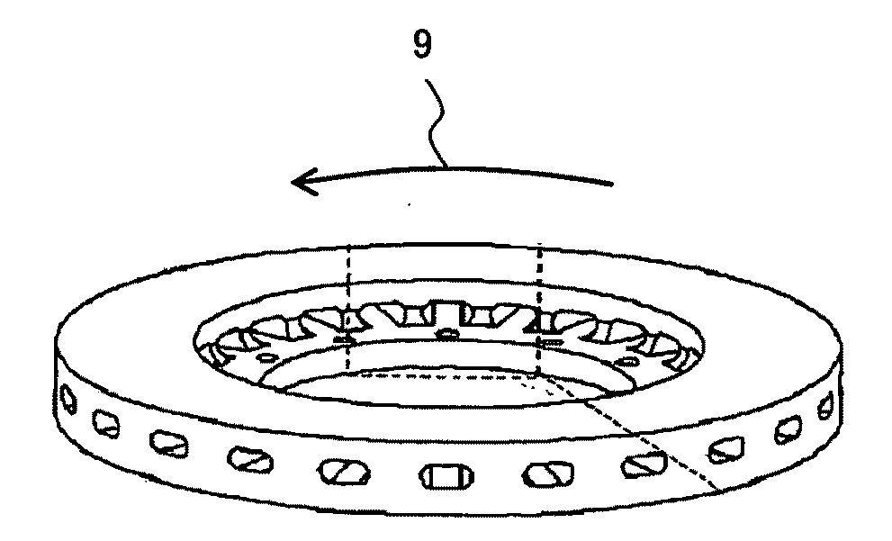
[0045]The first embodiment of the present invention is described below referring to FIGS. 8 and 9. FIG. 8 is a perspective view of the disc rotor according to the first embodiment where the whole disc rotor assembly including a bell housing 21 is shown. FIG. 9 shows a cross section of a disc rotor 20 and its vent hole shape in enlarged form. As the disc rotor material, an aluminum alloy with dispersed cast iron or ceramic particles or carbon fiber reinforced silicon carbide (C / SiC) is chosen. As the bell housing material, iron, aluminum alloy or titanium is chosen. Although FIG. 8 shows that the disc rotor 20 and bell housing 21 are separate from each other, it is also possible that the disc rotor 20 and bell housing 21 are integrally molded. Alternatively, the bell housing 21 may lie over the disc rotor 20 shown in FIG. 8.

[0046]The disc rotor 20 (FIG. 8) is connected to the bell housing 21 through pins (not shown) and the bell housing 21 is connected to the wheel (not shown). In br...

second embodiment

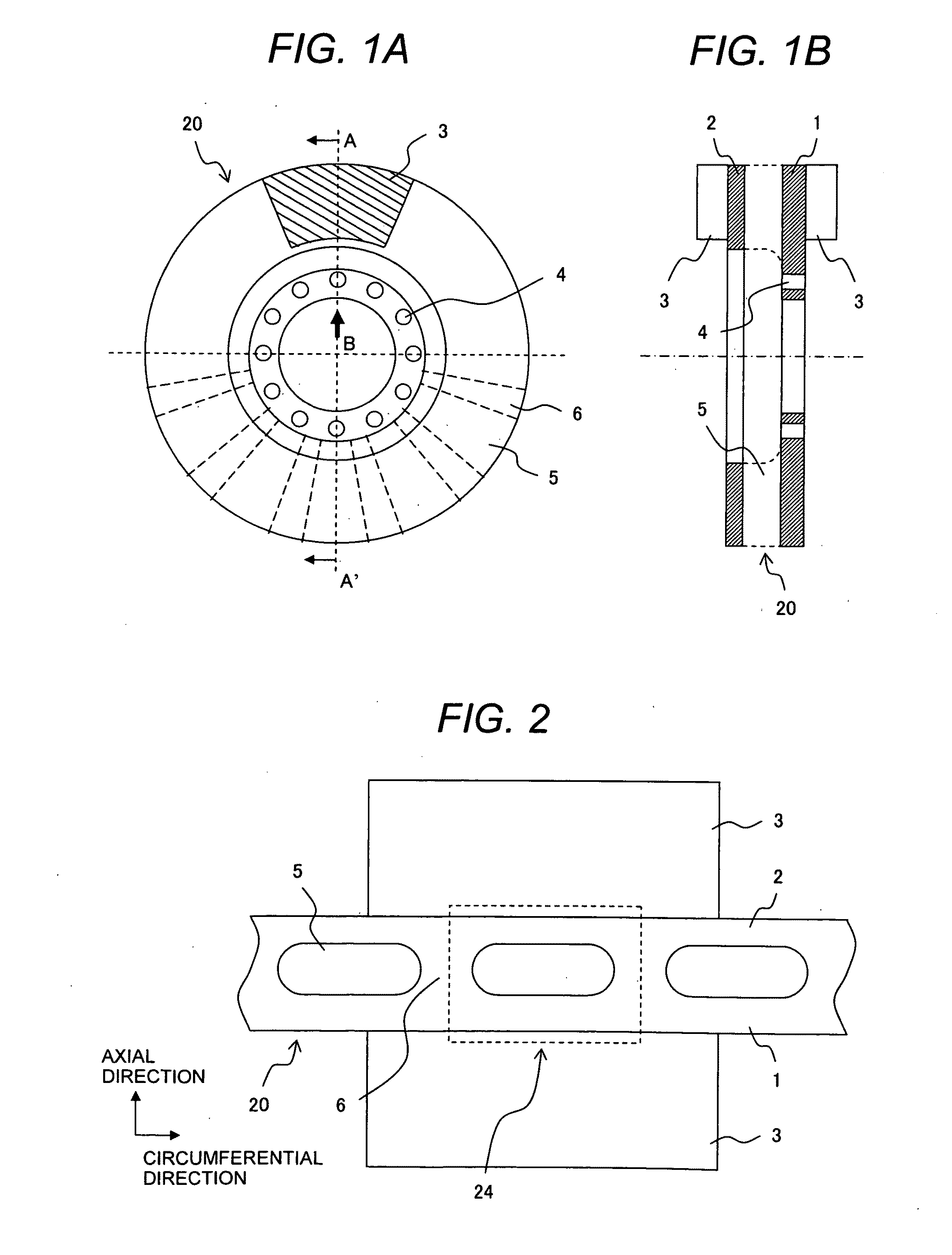
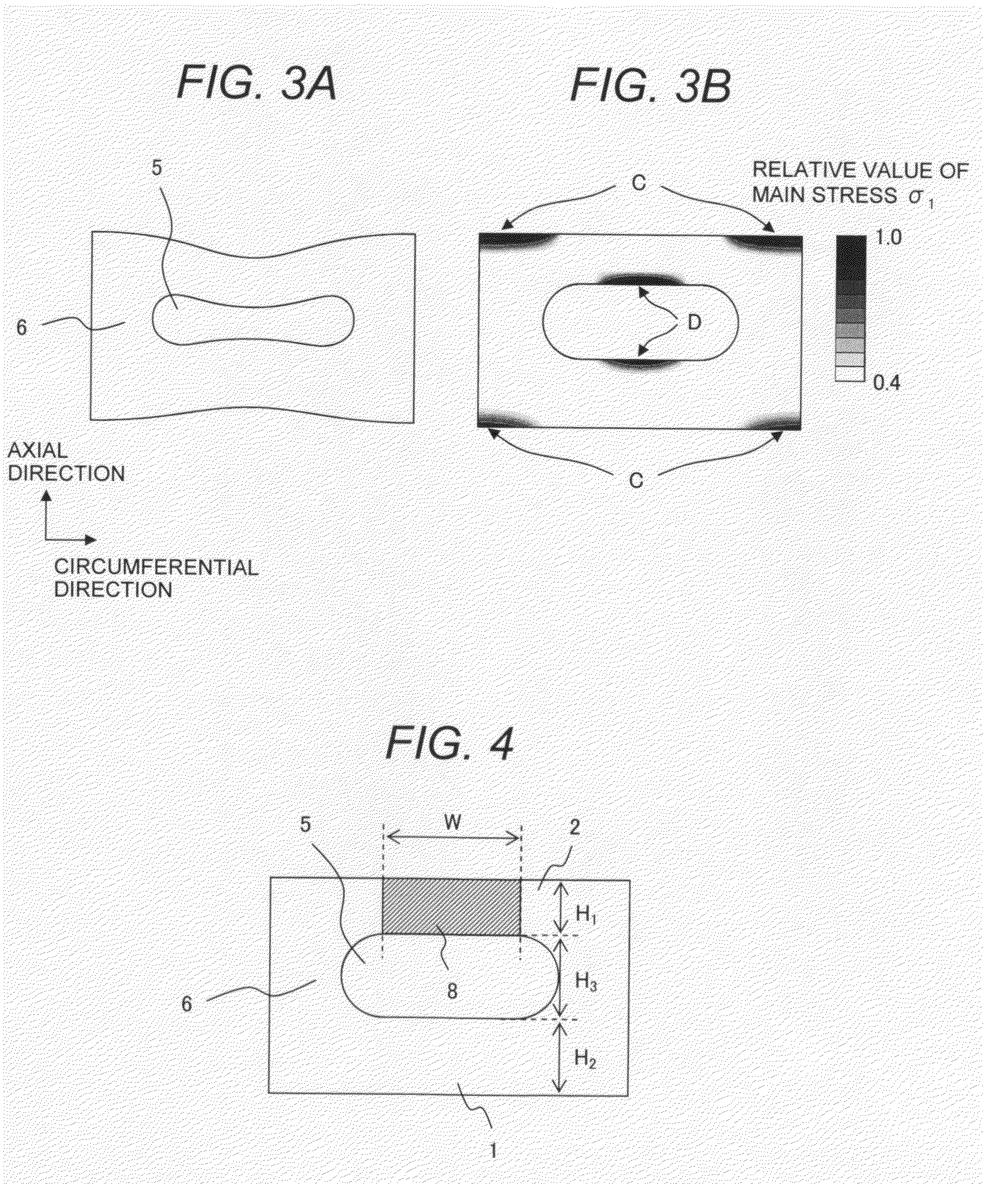
[0051]The second embodiment of the present invention will be described referring to FIG. 12 to FIG. 14C. FIG. 12 is a perspective view of a disc rotor shape according to the second embodiment where the whole disc rotor assembly including a bell housing 21 is shown. FIG. 13 shows a cross section of the disc rotor 20 and its vent hole shape in enlarged form. FIG. 14A shows the conventional vent hole shape, FIG. 14B shows the vent hole shape in this (second) embodiment, and FIG. 14C shows the vent hole shape in the first embodiment. Next, the vent hole shape (FIG. 14B) characteristic of this embodiment and its effect will be explained in detail.

[0052]First, the shape of the vent hole 5 is described below. As with the vent hole shape in the first embodiment (FIG. 14C), with the vent hole shape in the second embodiment (FIG. 14B), the radius R of the corner with relatively large torque stress (point G in FIG. 14B) is large and torque stress is thus smaller than with the conventional shap...


PUM


Abstract

A disc rotor for a disc brake with a vent hole shape which has an inner peripheral corner with a larger radius to reduce stress generated by braking torque and suppresses an increase in stress generated by pad pressure. The disc rotor includes a first sliding part connected to a bell housing, a second sliding part located parallel to, and spaced in an axle direction from, the first sliding part, a plurality of ribs circumferentially spaced between the sliding parts, and vent holes formed by the ribs and the sliding parts. The inner peripheral shape of each of the vent holes has at least two arc shapes with different curvature radii at an end perpendicular to the disc rotor's rotation direction. The smallest curvature radius is 2 mm or more. An arc curvature radius on the first sliding part side is larger than that on the second sliding part side.

Description

CLAIMS OF PRIORITY[0001]The present application claims priority from Japanese Patent application serial No. 2008-139837, filed on May 28, 2008, the content of which is hereby incorporated by reference into this application.FIELD OF THE INVENTION[0002]The present invention relates to disc rotors for disc brakes of vehicles.BACKGROUND OF THE INVENTION[0003]A disc brake is a kind of braking device as a vehicle component whereby frictional heat is generated by forcing brake pads against both sides of a disc (hereinafter called the disc rotor) rotating together with a wheel so that kinetic energy is converted into thermal energy to produce a braking effect. One example of such a disc rotor is illustrated in FIG. 20 of JP-A No. 2002-5207. Specifically a disc rotor 71 has fins 83 (hereinafter called the ribs) between a pair of sliding parts 75 and is fixed on a wheel through a main body 73 (hereinafter called the bell housing) having a hub 77. The sliding parts 75 have vent holes penetrati...

Claims


Application Information

Patent Timeline
Patent Type & Authority Applications(United States)
IPC IPC(8): F16D65/847
CPCF16D65/128F16D2065/1308F16D2200/0039F16D2200/0013F16D2065/1328F16D65/00F16D65/12
Inventor IGA, YOSHIHIKOMORIYA, HIROSHIEBIHARA, MAKOTOBABA, KAZUYA
Owner HITACHI CHEM CO LTD
Why Eureka
Try Eureka