
Integrated circuit package having integrated faraday shield

a technology of integrated circuits and faraday shields, applied in the direction of basic electric elements, electrical equipment, semiconductor devices, etc., can solve the problems of reducing reducing the size advantage originally obtained, and reducing so as to increase the increase the overall size of the package, and increase the number of applications in which the package is used

Active Publication Date: 2009-11-19
TEXAS INSTR INC
View PDF11 Cites 46 Cited by
  • Summary
  • Abstract
  • Description
  • Claims
  • Application Information

AI Technical Summary

Benefits of technology

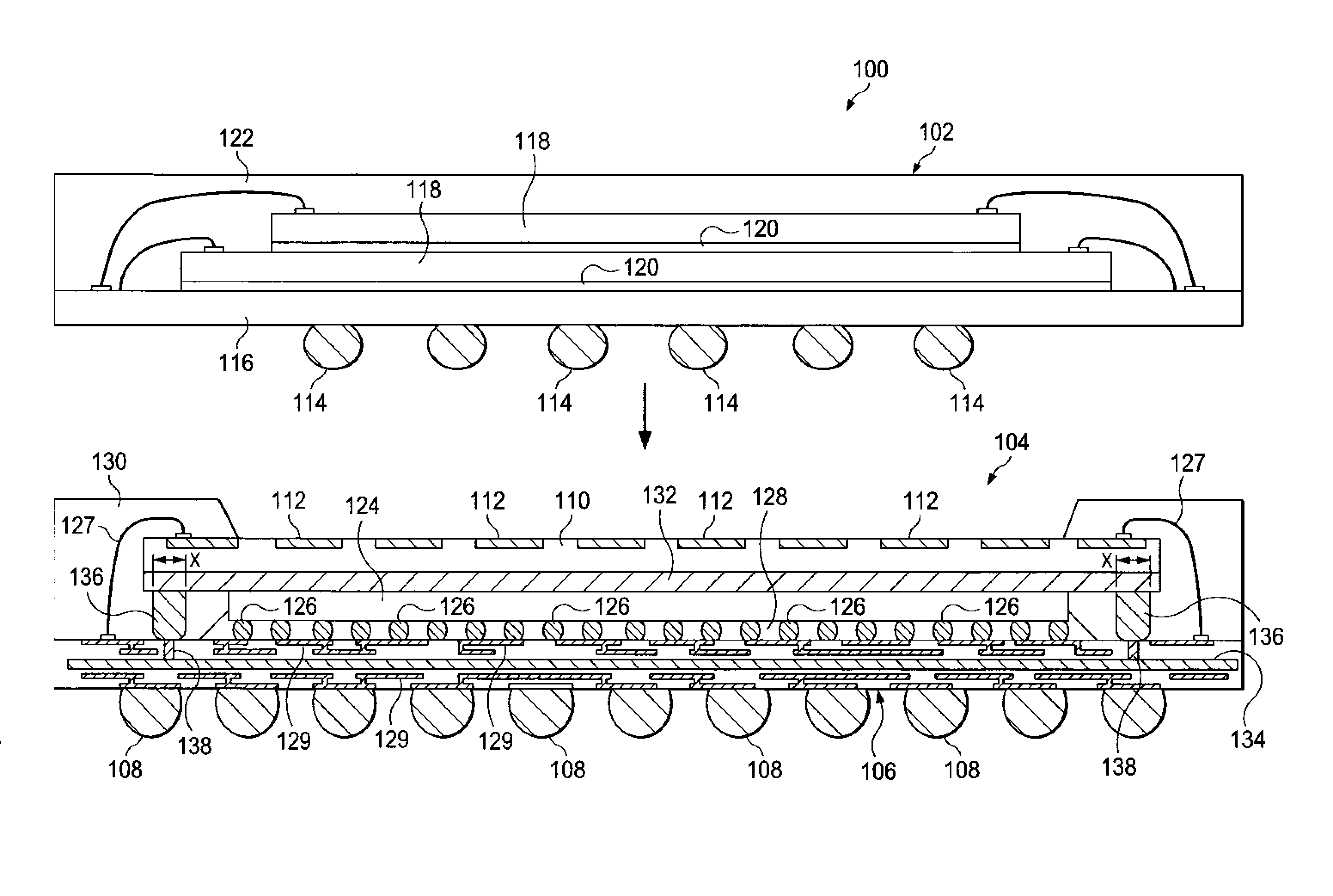
[0006]With the increasing popularity of stacked packing schemes, such as POP packaging, the number of applications in which they are used has also increased. However, incorporating EMI sensitive ICs into such packages has been difficult due to the increased dimensions resulting from the incorporation of Faraday cages. Even worse, if designers wish to incorporate an EMI generating IC and an EMI sensitive IC into a single POP package, the proximity of EMI generating IC may prevent doing so. For such packing technologies, the Present Inventors have found that the addition of conventional Faraday cage structures not only increases size of the POP packages, but also increases the cost and complexity for the packages and electronic devices they are used in. In response to these problems, embodiments of the present invention provide schemes for implementing Faraday cages in stacked ICs packages without the addition of a separate Faraday cage structure. In particular, the Present inventors have discovered that by incorporating shield layers into existing electronic substrates used for creating stackable packages and applying a polymer-comprising conductive epoxy to electrically contact the shield layers, a Faraday cage can be provided therebetween without increasing the overall dimensions of the package, and without the need for additional structures to be incorporated into the package.

Problems solved by technology

The electromagnetic energy radiated by such devices can interfere with the operation of other devices or circuits in the vicinity of the radiating IC, including those ICs in the same stacked package, and is therefore generally undesirable.
However, the use of conventional Faraday cages in stacked packaging schemes, such as POP packaging, typically increases the overall dimensions of the package and can eliminate at least a portion of the sizing advantages originally obtained through stacked packaging schemes.
However, incorporating EMI sensitive ICs into such packages has been difficult due to the increased dimensions resulting from the incorporation of Faraday cages.
Even worse, if designers wish to incorporate an EMI generating IC and an EMI sensitive IC into a single POP package, the proximity of EMI generating IC may prevent doing so.
For such packing technologies, the Present Inventors have found that the addition of conventional Faraday cage structures not only increases size of the POP packages, but also increases the cost and complexity for the packages and electronic devices they are used in.
However, while such techniques can be used effectively to shield multiple ICs in a planar arrangement, such techniques are typically impractical for shielding one or more individual stacked dies or packages.
In this conventional POP arrangement, EMI shielding between the top and bottom packages 102, 104 is generally not practical, as inserting additional structure between the packages can prohibitively increase the size of the stacked packages.
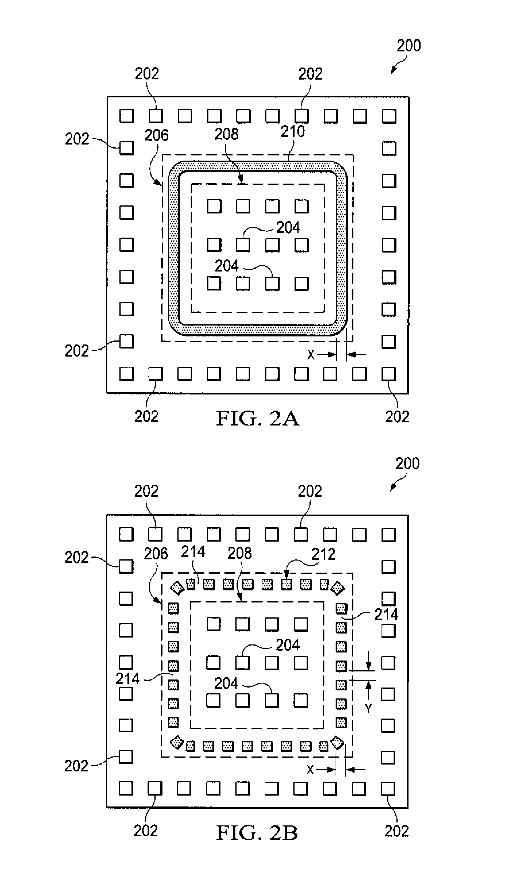
For example, in some cases, if a non-continuous bonding pattern is provided, the void size (y) may be sufficient to block EMI originating from an location exterior to the ICs, but not for blocking EMI between the ICs.

Method used


Image

  • Integrated circuit package having integrated faraday shield
  • Integrated circuit package having integrated faraday shield
  • Integrated circuit package having integrated faraday shield

Examples


Embodiment Construction

[0016]The present invention is described with reference to the attached figures, wherein like reference numerals are used throughout the figures to designate similar or equivalent elements. The figures are not drawn to scale and they are provided merely to illustrate the instant invention. Several aspects of the invention are described below with reference to example applications for illustration. It should be understood that numerous specific details, relationships, and methods are set forth to provide a full understanding of the invention. One having ordinary skill in the relevant art, however, will readily recognize that the invention can be practiced without one or more of the specific details or with other methods. In other instances, well-known structures or operations are not shown in detail to avoid obscuring the invention. The present invention is not limited by the illustrated ordering of acts or events, as some acts may occur in different orders and / or concurrently with o...


PUM


Abstract

A packaged integrated circuit (IC) (100) includes a first substrate (110) including a first plurality of layers and first circuit coupling features (112) at an upper surface of the first substrate (110). The first plurality of layers include a first electromagnetic interference shielding layer (132). The packaged IC also includes a second substrate (106) having an upper surface attached to a lower surface of the first substrate (110) by an electrically conductive adhesive material (136). The second substrate (106) includes a second plurality of layers and a second circuit coupling feature (108) at a lower surface of the second substrate (106). The first plurality of layers includes a second EMI shielding layer (134). The packaged IC further includes a functional die (124) disposed between the first (110) and the second (106) substrates and functionally coupled to the first (112) and / or the second (108) circuit coupling features. In the packaged IC, the adhesive material (136) electrically couples the first (132) and the second (134) shielding layers.

Description

FIELD OF THE INVENTION[0001]The present invention relates generally to integrated circuit packages and, more particularly, to structures and techniques for modulating electromagnetic interference in integrated circuit packages.BACKGROUND[0002]As the demand for faster, smaller electronic products with increased functionality is increased, some designers have turned to system-in-package (SIP) solutions. A SIP typically includes several different types of integrated circuits (ICs) integrated into a single IC package. However, in recent years, stacked packaging schemes, such as package-on-package (POP) configurations, have been used in place of SIP's. Typically, by allowing stacking of different semiconductor packages, the required footprint size for a semiconductor package in an electronic product can be reduced. Furthermore, because some stacked packages, such as POP packages, provide a modular solution by allowing different combinations semiconductor packages to be stacked, designers...

Claims


Application Information

Patent Timeline
IPC IPC(8): H05K9/00
CPCH01L23/49833H01L2924/15311H01L23/60H01L25/0655H01L25/0657H01L25/105H01L2224/48091H01L2224/48227H01L2224/73265H01L2225/06517H01L2225/0652H01L2225/06572H01L23/552H01L2225/1088H01L2225/1023H01L2225/1041H01L2225/1058H01L2224/73253H01L2924/3025H01L2924/1815H01L2224/73204H01L2224/32225H01L2224/32145H01L2224/16225H01L24/48H01L2924/00014H01L2924/00H01L2924/00012H01L24/73H01L2924/14H01L2924/181H01L2224/45099H01L2224/45015H01L2924/207
Inventor BEDDINGFIELD, STANLEY CRAIGDROUARD, JEAN-FRANCOIS
Owner TEXAS INSTR INC
Learn More