Fiber reinforcing texture for making a composite material part

a fiber reinforcement and composite material technology, applied in the field of fiber reinforcement texture for making composite material parts, can solve problems affecting the properties of composite materials, and achieve the effects of reducing surface irregularities, avoiding steep densification gradients, and reducing surface irregularities

Active Publication Date: 2009-11-12
SAFRAN CERAMICS SA
View PDF7 Cites 11 Cited by
  • Summary
  • Abstract
  • Description
  • Claims
  • Application Information

AI Technical Summary

Benefits of technology

[0009]Densification of the fiber texture by CVI is thus encouraged all the way to the core, while avoiding a steep densification gradient between the core and the skin, while at the skin a surface state is preserved that is free from significant irregularities.
[0010]In an embodiment, the core is made by interlock weaving, thereby providing easier access for the gas to the core of the preform, while the skin is made by weaving with a plain, satin, or twill type weave, thus serving to limit surface irregularities. The weaving of the skin may comprise 2D weaving, with the interlock weaving providing the interlacing between the weft layers all the way to the skin, or the weaving of the skin may comprise multi-layer 3D weaving.
[0011]In another embodiment, the core and the skin may be made by multi-layer 3D weaving using different weaves, for example a satin type weave in the core portion and a plain or twill type weave in the skin portion. A plain type weave in the skin gives easier access to gas through the skin compared with a satin type weave and thus encourages CVI densification all the way to the core.
[0012]In yet another embodiment, the skin is made with a structure having a lower count than the structure with which the core is made, thereby providing easier access for the gas through the skin towards the core of the preform.
[0013]It is possible to vary simultaneously the 3D weaving technique and the structure between the core and the skin.
[0014]It is also possible to form the various portions of the fiber texture with yarns of different chemical natures so as to give them particular desired properties, in particular resistance to wear or to oxidation.

Problems solved by technology

In the event of access being difficult to the pores in the fiber texture, or in the presence of pores of very different sizes, then the smaller pores become filled in more quickly and a strong densification gradient is inevitable, thereby affecting the properties of the composite material.

Method used


Image

  • Fiber reinforcing texture for making a composite material part
  • Fiber reinforcing texture for making a composite material part
  • Fiber reinforcing texture for making a composite material part

Examples


example 1

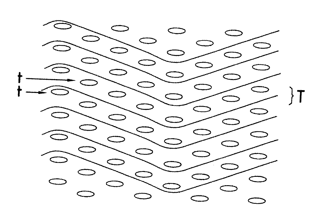
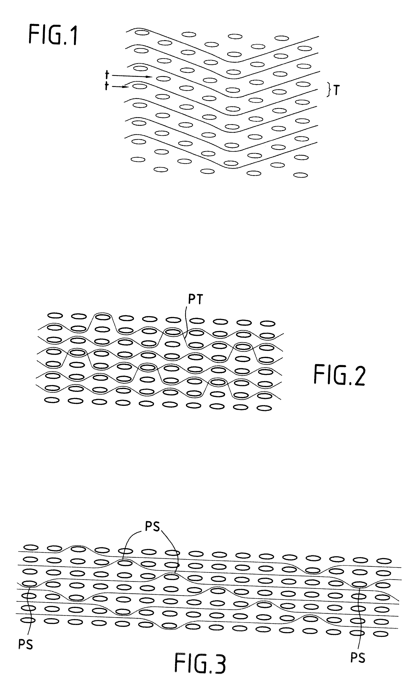
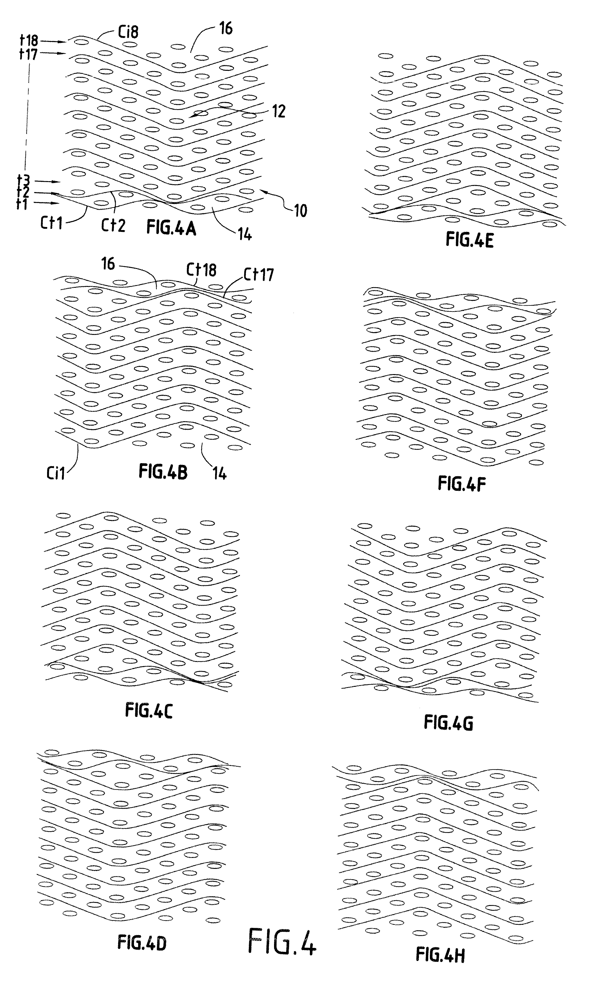
[0050]FIGS. 4A to 4H show portions of eight successive planes of a weave of a fiber structure obtained by 3D weaving, the weft yarns being shown in section.

[0051]The fiber structure 10 comprises nine layers of weft yarns, i.e. 18 half-layers t1 to t18. In the core 12 situated between the opposite skins 14 and 16, the 3D weaving is of the interlock type with yarns made up in the majority from discontinuous carbon fibers held by a covering yarn sacrificial material, as described in EP 0 489 637, and with a 10 / 10 structure per layer (10 yarns per centimeter in both the weft and the warp directions). The covering yarn is constituted, for example, by a soluble polymer such as a polyvinyl alcohol or a polymer that can be eliminated by heat treatment without affecting the carbon of the fibers, such as a polyethylene or a polyvinyl acetate. In the skins 14 and 16, the weaving is two-dimensional with a plain type weave using yarns made up from continuous carbon filaments and with a 5 / 5 struc...

example 2

[0054]FIGS. 5A to 5H show portions of successive planes of a fiber texture 20 obtained by 3D weaving, this texture differing from that of Example 1 in that multi-layer weaving is performed in the skins 24 and 26 with a weave analogous to a multiple plain weave over a thickness of two weft half-layers, the 3D weaving in the core portion 22 being of the interlock type with each warp yarn extending over a depth of three half-layers of weft yarns, the weft yarns being disposed in a staggered configuration.

[0055]When multi-layer weaving is performed in the skin, there is no need for the interlock weaving to cover all of the weft layers of the skin. It can suffice for a single weft layer or half-layer situated at the interface between the core and the skin to be involved both with the interlock weaving and with the multi-layer weaving in order to obtain interlacing by 3D weaving between all of the weft yarns. Nevertheless, in the example shown, the interlock weave involves all of the half...

example 3

[0057]FIGS. 6A to 6H show portions of successive weft planes in a texture 30 obtained by three-dimensional multi-layer weaving, this texture differing from that of Example 1 in that the same interlock 3D weaving is performed in the core 32 and in the skins 34 and 36.

[0058]In the core 32, the weaving is performed using yarns made up from discontinuous fibers united by a sacrificial covering yarn, whereas in the skins 34 and 36, i.e. over one or two extreme weft half-layers, the weaving is performed using yarns made up from continuous filaments. In the example shown, the yarns made up from continuous filaments are the yarns of the weft yarn half-layers t1, t1, t17, and t18, and the warp yarns that engage the yarns of the half-layers t1, t18 (warp yarns C1 and C7 in FIGS. 6B and 6A).

[0059]In this example only the type of yarn varies between the core and the skin.


PUM

PropertyMeasurementUnit
chemical naturesaaaaaaaaaa
cohesionaaaaaaaaaa
mechanical propertiesaaaaaaaaaa

Abstract

A fiber reinforcing texture (10) woven as a single part for fabricating a composite material part having an inner portion (12), or core, made by three-dimensional weaving with yarns made up from discontinuous fibers, and a portion (14, 16) adjacent to an outside surface, or skin, made by weaving with yarns made up from continuous filaments.

Description

BACKGROUND OF THE INVENTION[0001]The invention relates to making composite material parts and particularly to making fiber reinforcing textures for such parts.[0002]The field of application of the invention is more particularly making thermostructural composite material parts, i.e. parts made of a material having mechanical properties that make it suitable for constituting structural elements and having the ability to conserve these properties at high temperatures. Thermostructural composite materials are typically carbon / carbon (C / C) composite materials having carbon fiber reinforcement densified by a carbon matrix, and ceramic matrix composite (CMC) materials having refractory fiber reinforcement (carbon fiber or ceramic fiber) densified by a ceramic matrix. Thermostructural composite material parts are used in particular in the fields of aviation and space.[0003]For parts made of composite material that present a certain thickness, it is common practice to make the reinforcing te...

Claims


Application Information

Patent Timeline
Patent Type & Authority Applications(United States)
IPC IPC(8): B32B5/02
CPCB32B5/08D03D25/005C08J5/047Y10T442/3203Y10T442/2984Y10T442/3211Y10T442/3195B29B11/16D03D11/00D03D15/30
Inventor BOUILLON, ERICCHARLEUX, FRANCOISLOUCHET-POUILLERIE, CAROLINEBOUVIER, REMICOUPE, DOMINIQUE
Owner SAFRAN CERAMICS SA
Why Eureka
Try Eureka