
Device for heating, cooling and producing domestic hot water using a heat pump and low-temperature heat store

a technology of domestic hot water and heat storage, which is applied in the direction of refrigerating devices, energy-efficient heating/cooling, sustainable buildings, etc., can solve the problems of high consumption, low overall size, and high risk of freezing, and achieve low cost. , the effect of low overall siz

Inactive Publication Date: 2009-11-12
DUPRAZ ENERGIES
View PDF3 Cites 35 Cited by
  • Summary
  • Abstract
  • Description
  • Claims
  • Application Information

AI Technical Summary

Benefits of technology

[0014]The problem addressed by the present invention is that of designing a heating and / or air-conditioning device based on a heat pump that is both efficient under all climatic conditions and of low cost and low overall size in terms of installing the buried heat exchangers.
[0015]The invention aims in particular to increase substantially the efficiency of the buried heat exchangers, so as to confer on them high thermal efficiency for a volume that remains reasonable.

Problems solved by technology

1. they suffer from high consumption when the direct temperature (air or sun) is higher than that of the soil;
2. they necessitate the installation of large and costly heat exchangers:approximately 1 m depth per m2 heated for a vertical heat exchanger, which entails deep and costly drilling,approximately 2 m2 of area per m2 heated for a horizontal heat exchanger, which occupies an area that is often too large.
Failure to comply with good practice in respect of dimensions leads to thermal impoverishment of the soil with the risk of freezing, distortion or breakdown.
In particular, in dry soil, the buried heat exchanger has a very low thermal capacity and its thermal coupling with the surrounding soil is poor.
The heat pump then functions between hot and cold sources the difference in temperature between which increases, which degrades its efficiency.
Such installations are not entirely satisfactory because they need an antifreeze device for the outdoor heat exchanger and suffer from decreasing thermal and energy performance as the temperature of the outside air falls, thus necessitating another heating device for cold periods.
Such installations are not entirely satisfactory, on the one hand because the areas of the solar collectors must be very large, making them very costly, and on the other hand they necessitate another heating device for cold periods without sunshine.

Method used


Image

  • Device for heating, cooling and producing domestic hot water using a heat pump and low-temperature heat store
  • Device for heating, cooling and producing domestic hot water using a heat pump and low-temperature heat store
  • Device for heating, cooling and producing domestic hot water using a heat pump and low-temperature heat store

Examples


Embodiment Construction

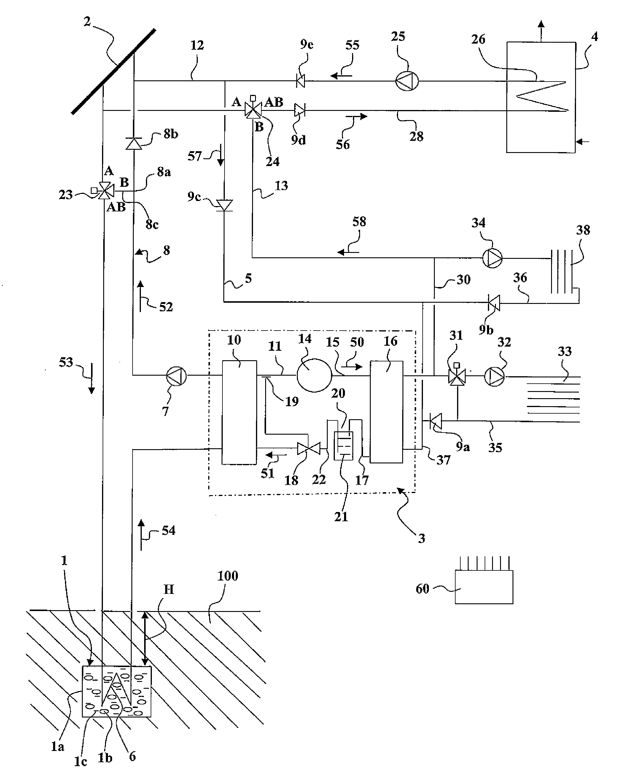
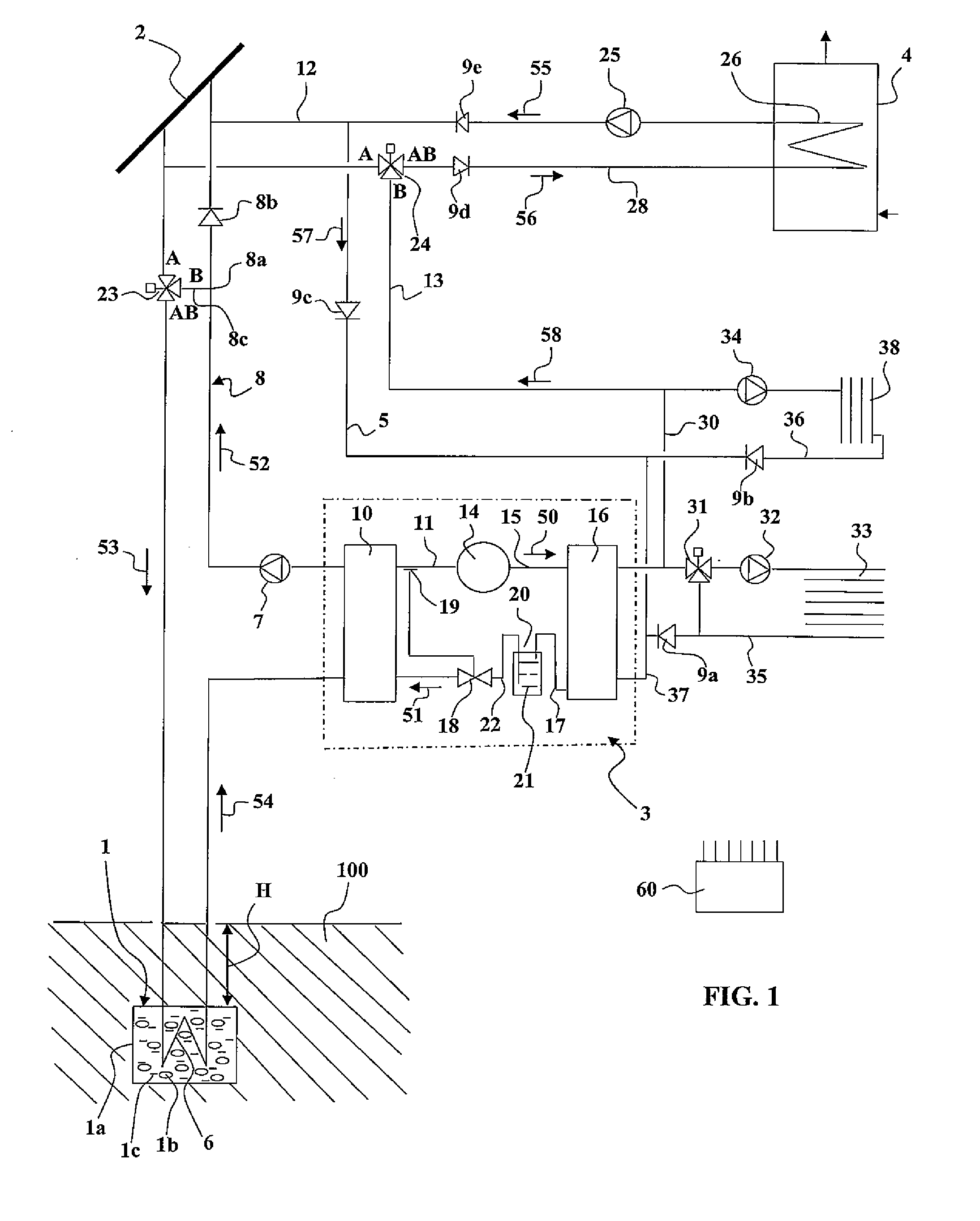
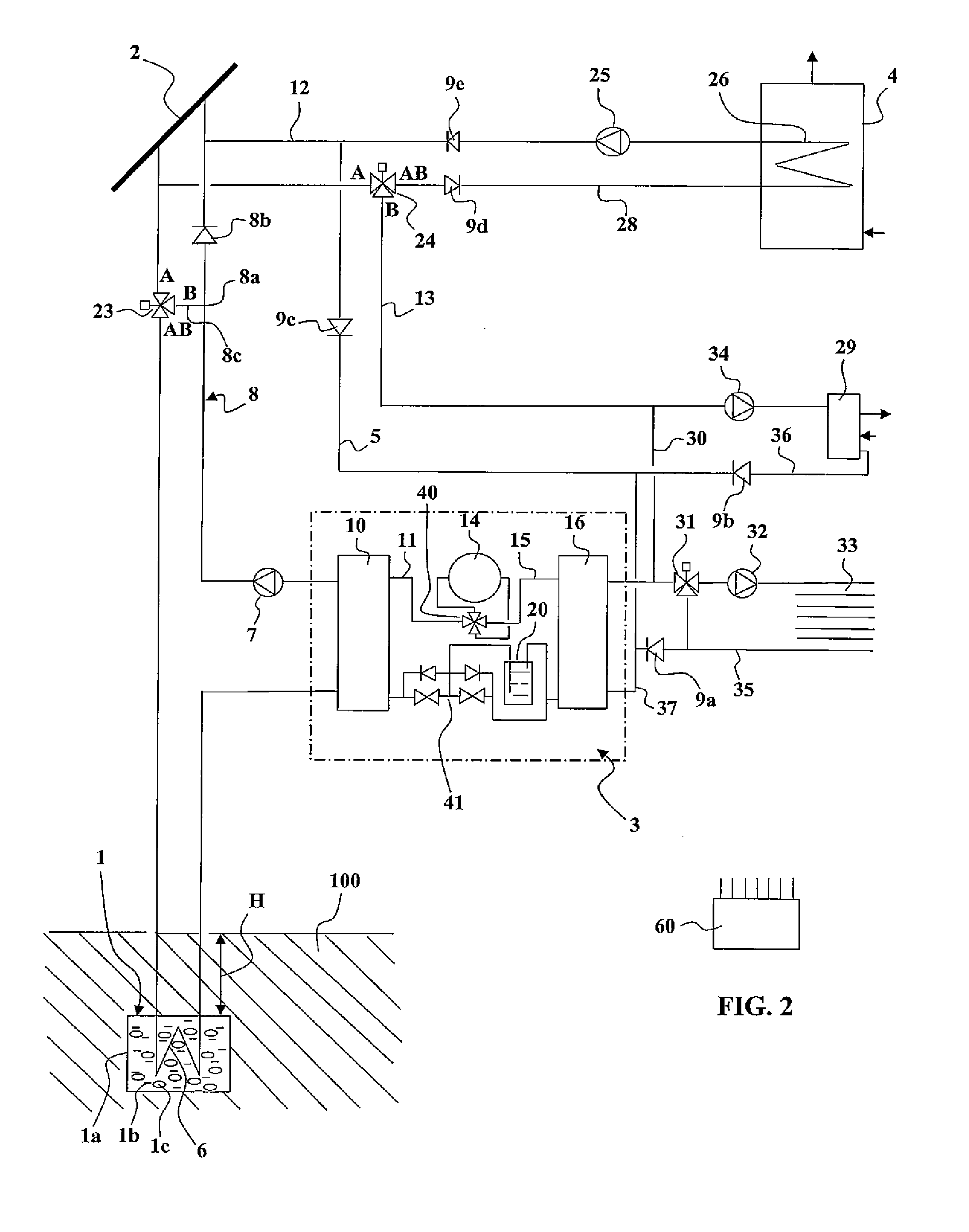
[0050]In the FIG. 1 embodiment, the heating and / or air conditioning device of the invention generally includes a thermal storage tank 1, a solar collector 2, a heat pump 3, means for providing thermal coupling between the heat pump 3, the thermal storage tank 1 and the solar collector 2, and means for providing thermal coupling between the heat pump 3 and the elements to be heated such as the atmosphere of the space or the domestic hot water.

[0051]The thermal storage tank 1 includes a pocket 1a buried in the soil 100, covered by a depth H of soil. The depth H is advantageously greater than or equal to approximately 1 m. Examples of thermal storage tank structures are described later. In all cases, the pocket 1a contains a permeable material 1b and water 1c.

[0052]In the embodiment shown, the thermal coupling between the heat pump 3 and the thermal storage tank 1 is provided by a collection circuit comprising a collection circulator pump 7 and a collection pipe 8 containing a collect...


PUM


Abstract

A heating device includes a low-temperature heat store thermally coupled to a heat pump. The heat store is a buried pocket containing a permeable material and water. A high heat exchange capacity is thus achieved by exploiting both the high specific heat of the water and the high latent heat of liquefaction of the water contained in the heat store.

Description

TECHNICAL FIELD OF THE INVENTION[0001]The present invention concerns heating systems, air conditioning systems and domestic hot water production devices for individual or collective space.[0002]The invention concerns more particularly heating devices with a heat pump and heat collector using a cold source and a hot source.[0003]Installations with a heat pump and buried heat exchanger for heating and producing domestic hot water for individual or collective space are known already. For example, the document FR 2 505 990 A1 describes one such installation with a solar collector and buried heat exchanger connected in series with a heat pump. In the above document, the buried heat exchanger, referred to as a geothermal energy collector, is a long buried pipe in which water flows. The pipe is therefore in direct contact with the soil in which it is buried.[0004]Such installations are not entirely satisfactory:[0005]1. they suffer from high consumption when the direct temperature (air or ...

Claims


Application Information

Patent Timeline
IPC IPC(8): F25B29/00F25B27/00F28D17/00
CPCF24D3/08F24D11/0221F28D20/0052Y02E60/142Y02B10/24Y02B10/70Y02B30/126Y02B10/20Y02B30/12Y02E60/14Y02A30/272
Inventor DUPRAZ, MICHEL LOUIS
Owner DUPRAZ ENERGIES
Learn More