
Anode and secondary battery

a secondary battery and anode technology, applied in the direction of non-aqueous electrolyte cells, cell components, sustainable manufacturing/processing, etc., can solve the problems of difficult to obtain sufficient cycle characteristics only by using electrical conductors, and increase electric power consumption, so as to achieve easy lowering of cycle characteristics, high performance, and easy increase of electric power consumption

Active Publication Date: 2009-10-29
MURATA MFG CO LTD
View PDF6 Cites 80 Cited by
  • Summary
  • Abstract
  • Description
  • Claims
  • Application Information

AI Technical Summary

Benefits of technology

[0010]In these years, the high performance and the multi functions of the portable electronic devices are increasingly developed, and the electric power consumption tends to be increased. Accordingly, charge and discharge of the secondary battery are frequently repeated, and thus the cycle characteristics are easily lowered. In such circumstances, to address recent demand for sufficient cycle characteristics of the secondary battery, it is difficult to obtain the sufficient cycle characteristics only by using an electrical conductor. Therefore, further improvement of the cycle characteristics of the secondary battery has been aspired.
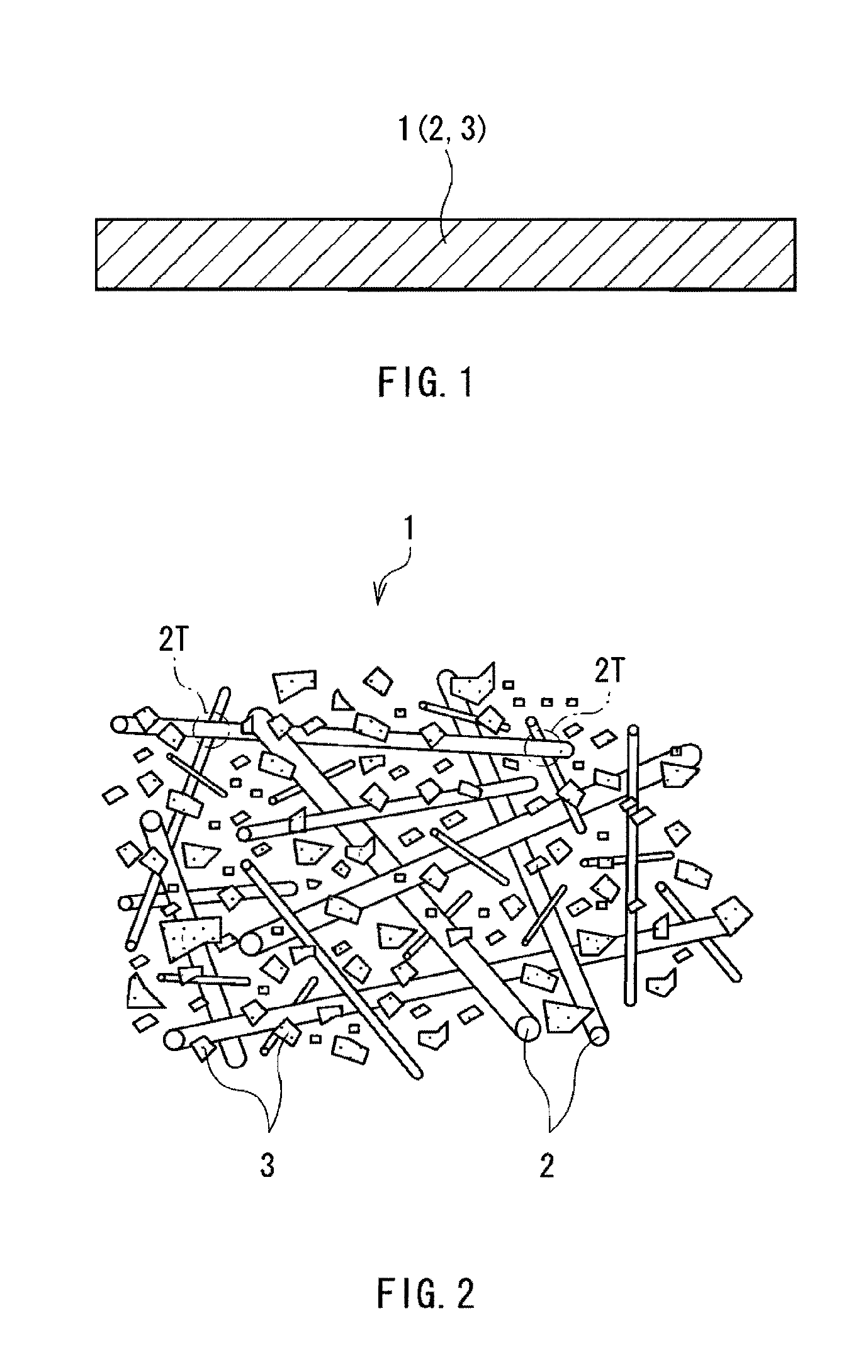
[0014]The anode of the embodiment of the invention contains the plurality of metal fibers forming the three-dimensional network structure and the plurality of anode active material particles having silicon. Thus, due to the plurality of metal fibers, sufficient conductive paths are obtained among the plurality of anode active material particles. Thus, compared to a general anode in which an active material layer is provided on a current collector made of a metal foil or the like, the current collectivity is improved. Thereby, according to the secondary battery including the anode of the embodiment of the invention, the cycle characteristics are able to be improved.

Problems solved by technology

In these years, the high performance and the multi functions of the portable electronic devices are increasingly developed, and the electric power consumption tends to be increased.
In such circumstances, to address recent demand for sufficient cycle characteristics of the secondary battery, it is difficult to obtain the sufficient cycle characteristics only by using an electrical conductor.

Method used


Image

  • Anode and secondary battery
  • Anode and secondary battery
  • Anode and secondary battery

Examples


example 1-1

[0179]The laminated film secondary battery illustrated in FIG. 9 and FIG. 10 was manufactured by the following procedure. At that time, the secondary battery was manufactured as a lithium ion secondary battery in which the capacity of the anode 54 was expressed based on insertion and extraction of lithium.

[0180]First, the cathode 53 was formed. First, lithium carbonate (Li2CO3) and cobalt carbonate (CoCO3) were mixed at a molar ratio of 0.5:1. After that, the mixture was fired in the air at 900 deg C. for 5 hours. Thereby, lithium cobalt complex oxide (LiCoO2) was obtained. Subsequently, 91 parts by mass of the lithium cobalt complex oxide as a cathode active material, 3 parts by mass of polyvinylidene fluoride as a cathode binder, and 6 parts by mass of graphite as a cathode electrical conductor were mixed to obtain a cathode mixture. After that, the cathode mixture was dispersed in N-methyl-2-pyrrolidone to obtain paste cathode mixture slurry. Finally, both faces of the cathode cu...

examples 1-2 to 1-9

[0185]A procedure was performed in the same manner as that of Example 1-1, except that as a component material of the metal fibers, titanium (Ti: Example 1-2), copper (Cu: Example 1-3), aluminum (Al: Example 1-4), zinc (Zn: Example 1-5), silver (Ag: Example 1-6), cobalt (Co: Example 1-7), nickel (Ni: Example 1-8), or chromium (Cr: Example 1-9) was used.

examples 2-1 to 2-13

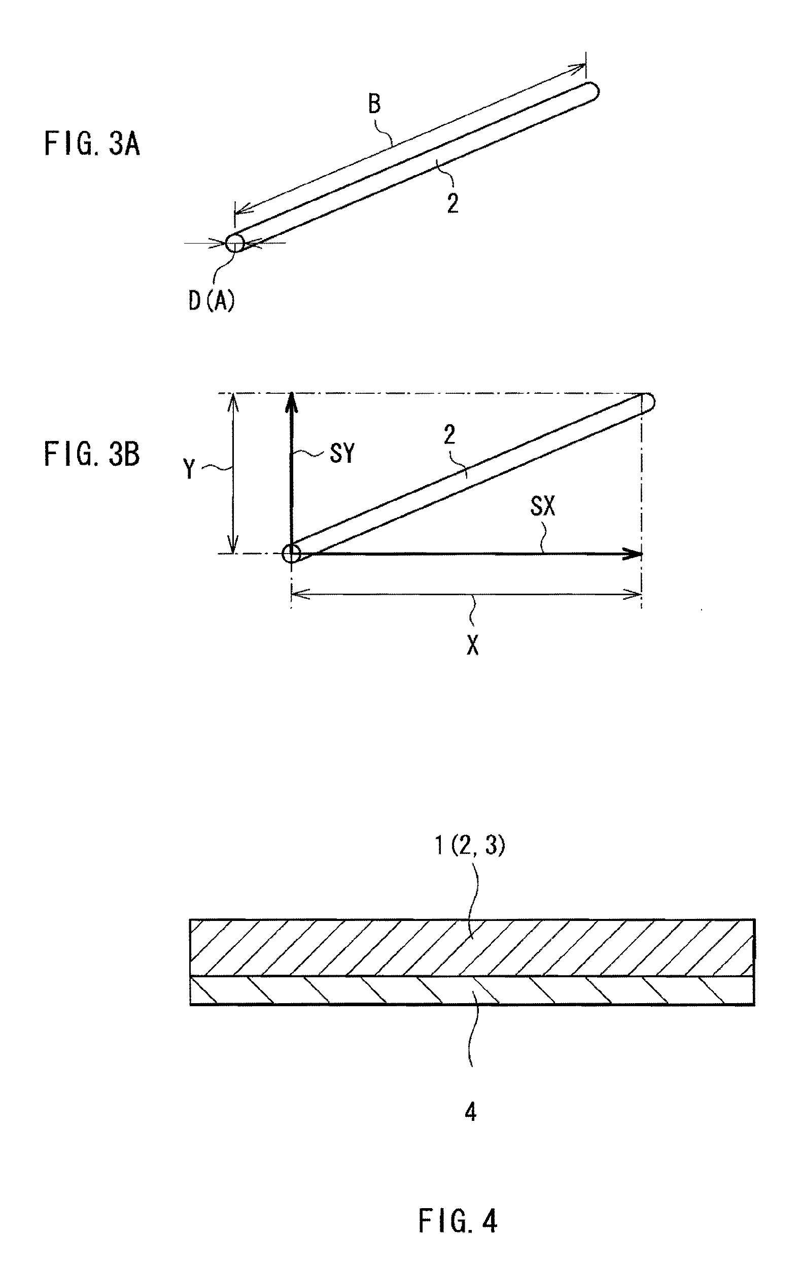
[0194]A procedure was performed in the same manner as that of Example 1-1, except that the diameter D of the metal fibers was 0.1 μm (Example 2-1), 0.3 μm (Example 2-2), 0.5 μm (Example 2-3), 1 μm (Example 2-4), 2 μm (Example 2-5), 5 μm (Example 2-6), 10 μm (Example 2-7), 20 μm (Example 2-8), 30 μm (Example 2-9), 40 μm (Example 2-10), 50 μm (Example 2-11), 60 μm (Example 2-12), or 70 μm (Example 2-13).

[0195]The cycle characteristics for the secondary batteries of Examples 2-1 to 2-13 were examined. The results shown in Table 2 and FIG. 14 were obtained.

TABLE 2Anode active material: siliconAnodeactivematerialDischargeparticlescapacityAnodeMetal fiberMedianretentioncurrentDiameter DsizeAnoderatiocollectorType(μm)Ratio B / A(μm)binder(%)Example 2-1CuFe0.1155PI40Example 2-20.342Example 2-30.570Example 2-4172Example 2-5275Example 2-6578Example 2-71079Example 1-11580Example 2-82081Example 2-93082Example40822-10Example50822-11Example60822-12Example70822-13ComparativeCu———5PI32example 1

[0196]...


PUM


Abstract

A secondary battery capable of improving the cycle characteristics is provided. The secondary battery includes a cathode, an anode, and an electrolytic solution. The electrolytic solution is impregnated in a separator provided between the cathode and the anode. The anode has an anode structure on an anode current collector. The anode structure has a structure in which a plurality of anode active material particles having silicon are held by a plurality of metal fibers forming a three-dimensional network structure. Due to the plurality of metal fibers, sufficient conductive paths are obtained among the plurality of anode active material particles. Thus, compared to a general anode in which an active material layer is provided on a current collector made of a metal foil or the like, the current collectivity is improved.

Description

BACKGROUND OF THE INVENTION[0001]1. Field of the Invention[0002]The present invention relates to an anode containing a plurality of anode active material particles and a secondary battery including the anode.[0003]2. Description of the Related Art[0004]In recent years, portable electronic devices such as video cameras, mobile phones, and notebook personal computers have been widely used, and it is strongly demanded to reduce their size and weight and to achieve their long life. Accordingly, as an electric power source for the portable electronic devices, a battery, in particular a light-weight secondary batter capable of providing a high energy density has been developed.[0005]Specially, a secondary battery using insertion and extraction of lithium for charge and discharge reaction (so-called lithium ion secondary battery) is extremely prospective, since such a secondary battery is able to provide a higher energy density than a lead battery and a nickel cadmium battery. The lithium ...

Claims


Application Information

Patent Timeline
IPC IPC(8): H01M10/26H01M4/36H01M4/38H01M4/13H01M4/134H01M4/62H01M4/70H01M10/052H01M10/0566H01M10/0567H01M10/0568H01M10/0569
CPCH01M4/134H01M4/621H01M4/624H01M4/626Y02E60/122H01M10/0569H01M10/0587H01M2300/0037H01M10/0525Y02E60/10Y02P70/50H01M4/02H01M4/38H01M4/62H01M10/05H01M2004/027
Inventor HIROSE, TAKAKAZUKAWASE, KENICHITAKADA, TOMOONOGUCHI, KAZUNORIFUJII, TAKAYUKI
Owner MURATA MFG CO LTD
Learn More