
Land clearing device

a land clearing and blade technology, applied in the direction of bearings, cutting implements, toothed gearings, etc., can solve the problems of ineffectiveness, high cost, damage to the blades of the land clearing device,

Inactive Publication Date: 2009-10-15
MENSE
View PDF16 Cites 0 Cited by
  • Summary
  • Abstract
  • Description
  • Claims
  • Application Information

AI Technical Summary

Benefits of technology

[0007]The land clearing device in accordance with the invention is intended for use in conjunction with a hydraulic boom crane as connected to its head. The land clearing device comprises a body which can be connected to the head of the hydraulic boom crane, a hydraulic motor supported on the body, and a blade operated by the hydraulic motor. In accordance with the invention, two elongated blade guides are supported on the body, which guides may be plate-like, rod-like, or bar-like elements, providing appropriate rigidity to the construction. The space between the blade guides comprises two blade panels, reciprocating at the same pace and in opposite directions and connected to the hydraulic motor. Furthermore, both blade panels comprise knife-like blade rows flush with each other, extending in opposite directions.
[0009]In another embodiment of the invention, the blades in the blade rows comprise cutting and knife-like sides and a milling point construction, which enables cutting of considerably thick trunks even more efficiently than the sharp sawing points. The milling blades preferably comprise chisel-like blades which point to both working directions, said blades being either slanted or perpendicular with respect to the direction of motion and working chippingly to effectively mill and cut even a thicker trunk. Such blades do not reject any thick trees encountered, but instead efficiently stick to the trunk and cut it.
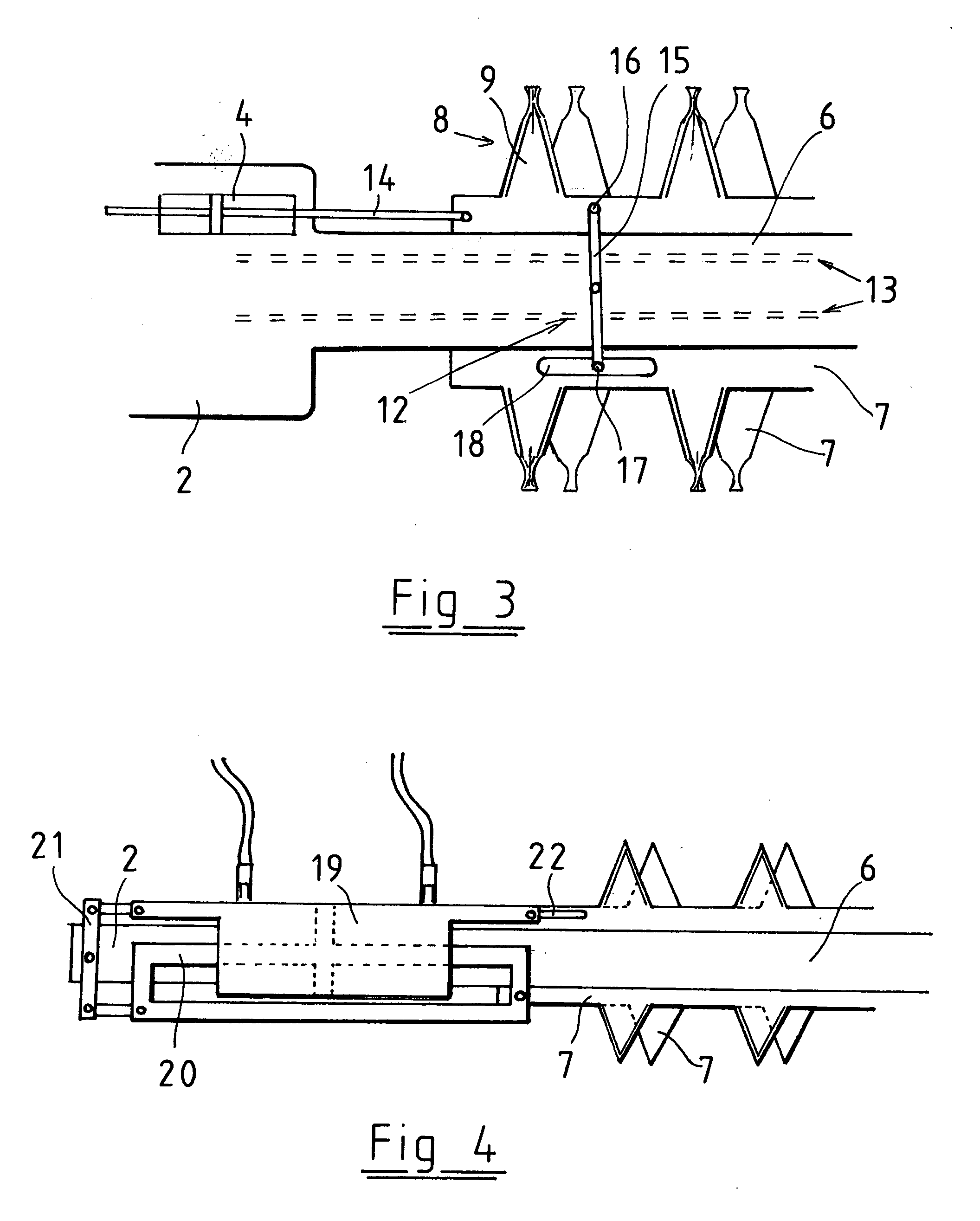
[0012]A solution in which the hydraulic motor is a double hydraulic cylinder to which the blade panels are connected in order to reciprocate them has revealed itself as a preferred embodiment. In this case, the hydraulic cylinder provides significant advantages. It is light and compact and provides per se a straight reciprocating movement, so that any crank constructions or other changes to the movement of force are not required. Furthermore, the use of the double hydraulic cylinder in which the cylinder capacity is equal on both sides of the piston ensures a reciprocating movement of the blade panels at an equal speed and without any jerking. Also in the operation by a hydraulic cylinder, only one of the blades can be connected to the hydraulic cylinder, in which case the blades can be interconnected by means of a suitable synchronizing arrangement, such as a lever mechanism, for their simultaneous movement in opposite directions.
[0016]The land clearing device in accordance with the invention provides significant advantages compared to the prior art. The structure of the land clearing device is simple and reliable. It is compact and light, so it can be efficiently used at the head of boom assemblies as long as 10 meters even in relatively small working machines. The blade construction is strong and suitable for clearing, cutting and trimming of all types of biomaterials. Due to its lightness and compact size, it is suitable, when used manually, for working on hedges and other plants for their cutting and shaping.

Problems solved by technology

Furthermore, the surface of the land intended for clearing may vary, comprising stubs, rocks and other such obstacles which easily damage the blades of the land clearing device.
The most significant problem of the clearing saw is its ineffectiveness and therefore its expensiveness.
In automated land clearance, chain crushers or rotating and cutting blade rows are used in working machines as connected to the boom assembly, but these machines are not, however, applicable to all uses.
Firstly, the quality of their work is often messy.
They may pose a danger when used in urban settlements, because the fast rotating blades may throw soil, rocks and wood chips or pieces of the blades that can reach very far.
Also, the blades must be repaired or replaced relatively often if the land clearing conditions become even slightly more difficult.
Furthermore, said land clearing devices are relatively large and heavy, so their operation requires large and heavy, and therefore space-consuming, working machines, which accordingly leave their marks for example in young stands and in areas intended for landscaping.

Method used


Image

  • Land clearing device
  • Land clearing device
  • Land clearing device

Examples


Embodiment Construction

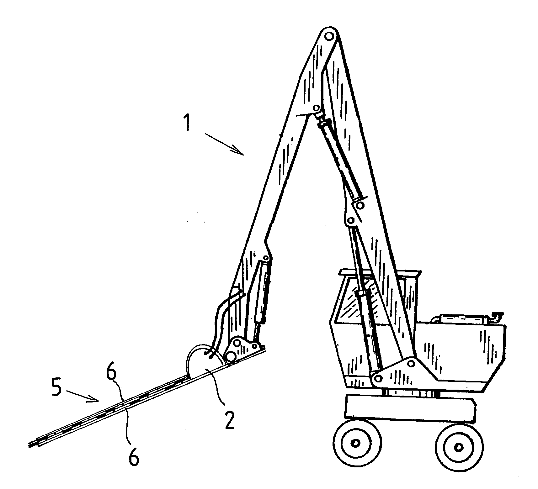
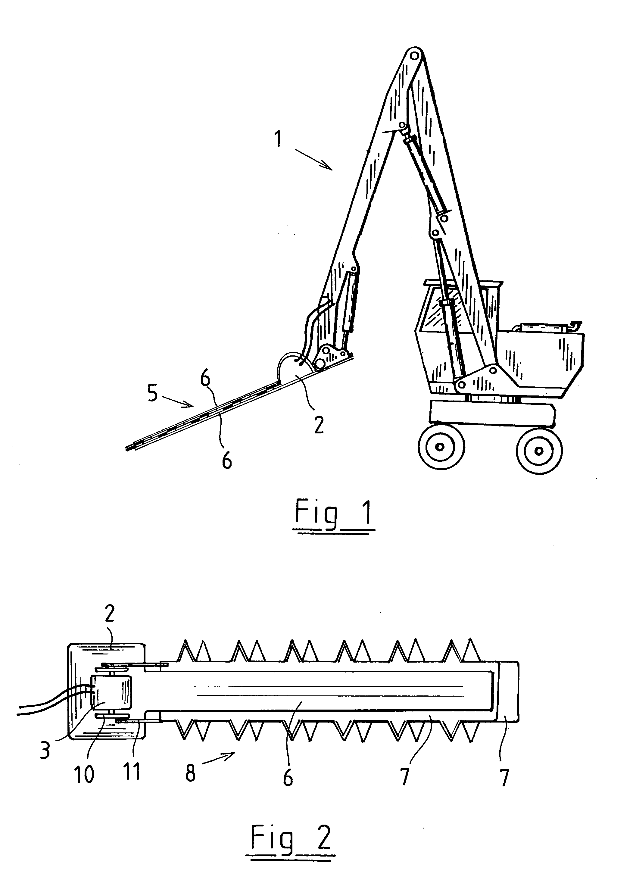
[0023]FIG. 1 represents a general view of the connection of the land clearing device in accordance with the invention to the head of a hydraulic boom assembly construction 1 as connected to a working machine, and its operation. Depending on the required working distance and the working machine used, the length of the boom assembly and the number of joints may vary freely. The substantial feature of the land clearing device in accordance with the invention is that it does not limit the selected working direction. The land clearing device can be used freely in horizontal direction, vertical direction and at different angles at the required heights, within the rotation limits of the joint construction of the boom assembly.

[0024]In the embodiment of FIG. 2, the land clearing device comprises a body 2 from which it can be connected to the boom assembly of the working machine. Two straight, plate-like and elongated blade guides 6 (both shown in FIG. 1) are connected to the body 2. Between...


PUM


Abstract

A land clearing device for use in conjunction with a hydraulic boom crane includes a body (2) which can be connected to the head of the hydraulic boom crane (1), a hydraulic motor (3,4), supported on the body, and a blade (5), operated by the hydraulic motor. In accordance with the invention, two elongated blade guides (6) are supported on the body (2), with two blade panels (7), reciprocating at the same pace and in opposite directions, supported between the blade guides, which blade panels are connected to the hydraulic motor (3,4) and both include knife-like blade rows (8), extending flush with each other in opposite directions.

Description

FIELD OF THE INVENTION[0001]The invention relates to the land clearing device as defined in the preamble of claim 1.BACKGROUND OF THE INVENTION[0002]The idea for the invention arose from the ever-growing need for clearance in coppices, young stands, and forestry lands in general, along power lines, on the roadsides, in the parks, along outdoor routes, and in the field of landscape management, which is catching on vastly. In all these applications, the vegetation intended for clearing may vary greatly from slight grass to dense willow-herb or raspberry vegetation, from single bushes to vast willow-tree thickets, or from thin brushwood even to relatively thick trees. Furthermore, the surface of the land intended for clearing may vary, comprising stubs, rocks and other such obstacles which easily damage the blades of the land clearing device.[0003]The most typical land clearing device is a portable clearing saw, in which a sawing blade, a cutting blade, or a steel or nylon wire can be ...

Claims


Application Information

Patent Timeline
Patent Type & Authority Applications(United States)
IPC IPC(8): A01G23/00F16H25/18F16N1/00F16C7/00F16H47/00
CPCA01G3/08A01G23/00Y10T74/2142Y10T74/18888Y10T74/19149Y10T74/18744
Inventor MENTULA, SEPPO ENSIO
Owner MENSE
Learn More