Information recording medium and method for production thereof

a technology of information recording and information, applied in the field of writeonce information recording medium, can solve the problems of reducing the production cost, affecting the quality of information recording, so as to reduce the production cost, reduce the transmission difference, and the effect of less expensiv

Inactive Publication Date: 2009-09-24
PANASONIC CORP
View PDF6 Cites 6 Cited by
  • Summary
  • Abstract
  • Description
  • Claims
  • Application Information

AI Technical Summary

Benefits of technology

[0012]The present invention is intended to provide an information recording medium and a method for production thereof that enable the transmittance difference between a recorded region and an unrecorded region of an information layer to be reduced while allowing the production cost to be reduced.
[0015]The information recording medium of the present invention and the method for production thereof enable the transmittance difference between a recorded region and an unrecorded region of an information layer to be reduced while allowing the production cost to be reduced. Therefore, the present invention can provide a multilayer information recording medium that is less expensive and capable of accurate recording and reproducing.

Problems solved by technology

In the case of using the TeOx recording material, there was a problem that it took some time to obtain a state where the signals can be detected after being recorded.
Therefore, it becomes difficult for the laser beam having been transmitted through the closer information layer(s) to record or reproduce accurately signals on or from the information layer located farther.
This problem becomes more serious when a larger number of information layers are stacked.
However, there has been a problem that in write-once information recording media using a Te—O—Pd recording material, the transmittance difference cannot be made small enough only by adjusting the material and thickness of the dielectric layers included in the information layers.
At the same time, there has been a problem that one information layer needs to include at least four layers, leading to an increased production cost.
This problem also becomes more serious when a larger number of information layers are stacked.

Method used


Image

  • Information recording medium and method for production thereof
  • Information recording medium and method for production thereof
  • Information recording medium and method for production thereof

Examples


example 1

[0057]In Example 1, information recording media were prepared having the same layer structure as that of the information recording medium 6 shown in FIG. 3, except that the reflective layer was eliminated.

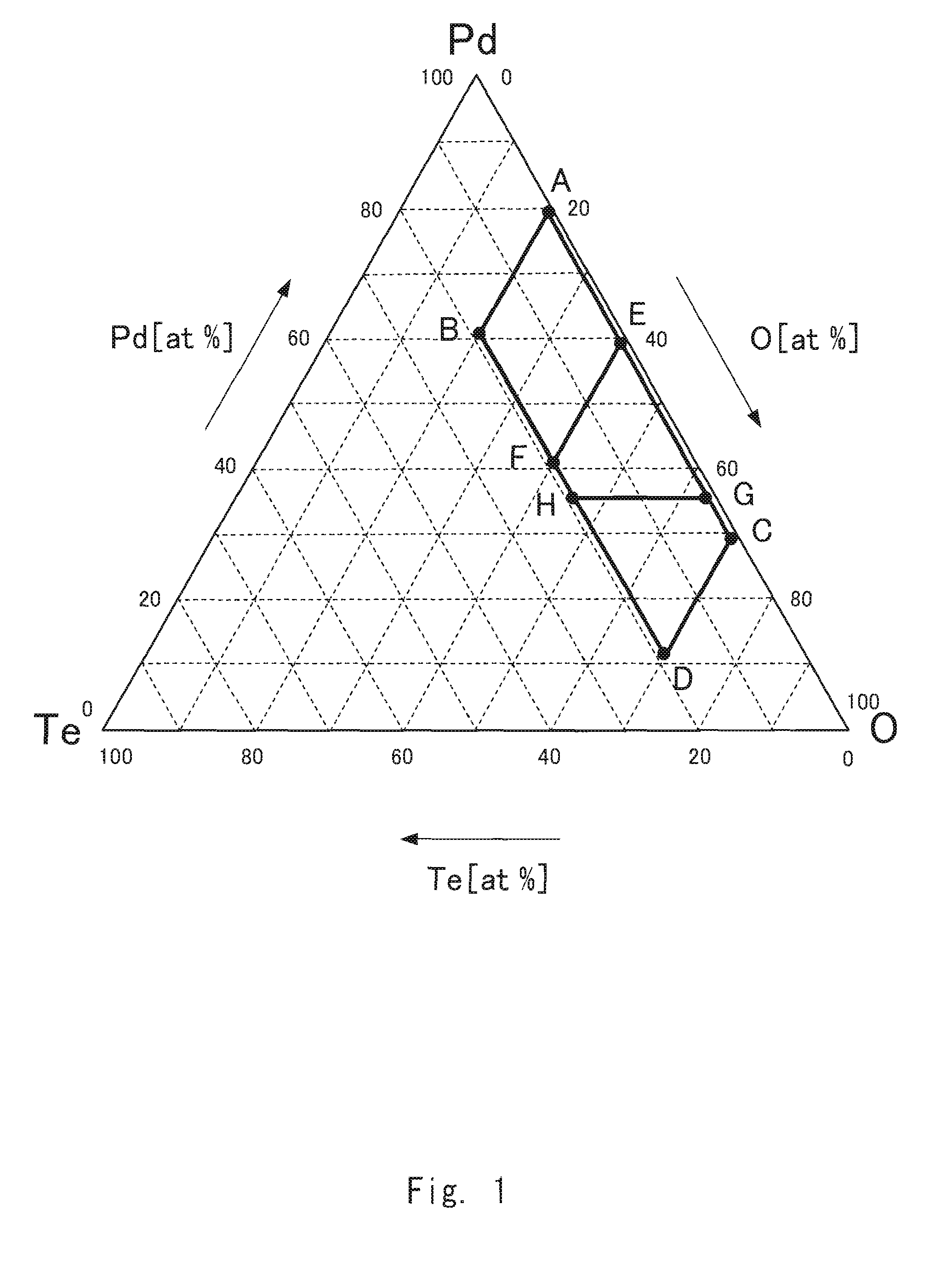
[0058]In the present example, investigation was made for a case where the recording layer composed of a Te—O—Pd material is used, where Pd is used as the element M.

[0059]A ZnS—SiO2 dielectric layer with a thickness of 20 nm was formed using a ZnS—SiO2 target, a recording layer with a thickness of 10 nm composed of Te—O—Pd material was formed in an atmosphere of sputtering gas composed of Ar (0 to 50 sccm) and O2 (5 to 50 sccm) using a target composed of Te—Pd, a ZnS—SiO2 dielectric layer with a thickness of 30 nm was formed using a ZnS—SiO2 target, on a 1.2 mm-thick transparent substrate formed of a polycarbonate resin, the substrate having a laser beam guiding groove with a groove pitch of 0.32 μm. These layers were formed in this order by a sputtering method.

[0060]An optically tr...

example 2

[0076]In Example 2, information recording media were prepared having the same layer structure as that of the information recording medium 6 shown in FIG. 3, except that the reflective layer was eliminated. The Te—O-M material was used for producing the recording layer, where element M was not Pd as in Example 1, but Ru, Rh, Ag, Re, Os, Ir, Pt, and Au.

[0077]A ZnS—SiO2 dielectric layer with a thickness of 20 nm was formed using a ZnS—SiO2 target, a recording layer with a thickness of 10 nm composed of Te—O-M was formed using a target composed of Te-M, where M denotes any of Ru, Rh, Ag, Re, Os, Ir, Pt and Au in the present example, in an atmosphere of sputtering gas of Ar (0 to 50 sccm) and O2 (5 to 50 sccm), and a ZnS—SiO2 dielectric layer with a thickness of 30 nm was formed using a ZnS—SiO2 target, on a 1.2 mm-thick transparent substrate formed of a polycarbonate resin, the substrate having a laser beam guiding groove with a groove pitch of 0.32 μm. These layers were formed in this ...

example 3

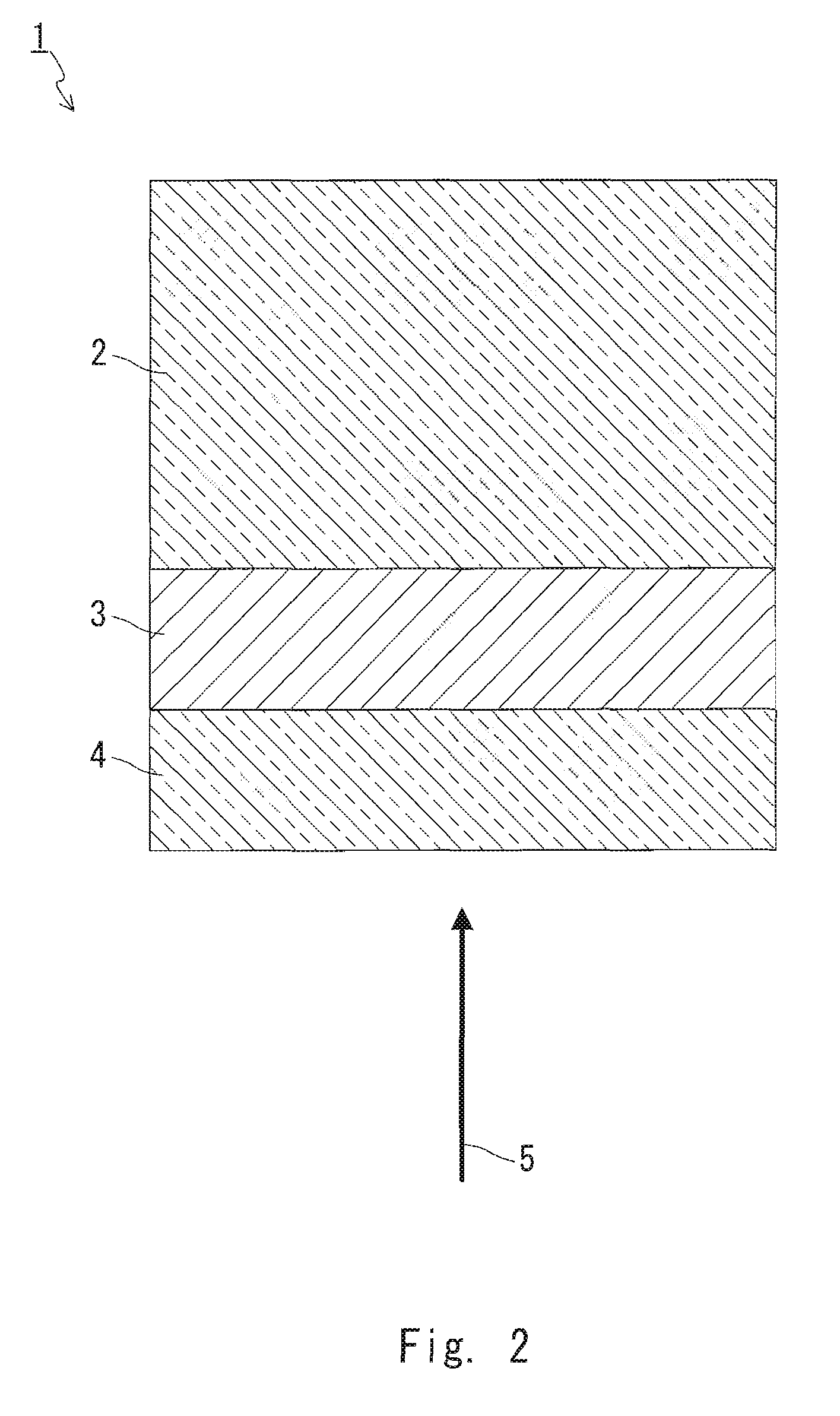
[0081]In Example 3, an information recording medium having the same layer structure as that of the information recording medium 1 shown in FIG. 2 was prepared.

[0082]A recording layer composed of Te—O—Pd with a thickness of 20 nm was formed using a target composed of Te—Pd, in an atmosphere of sputtering gas of Ar and O2, on a 1.2 mm-thick transparent substrate formed of a polycarbonate resin, the substrate having a laser beam guiding groove with a groove pitch of 0.32 μm. An optically transparent layer with a thickness of 100 μm was formed on a surface thereof using an ultraviolet curable resin transparent with respect to the laser beam (Disc 23). The composition of the recording layer was the same as that of Disc 6 in Example 1.

[0083]Disc 23 was evaluated for the initial C / N ratio, the amount of C / N ratio deterioration after the accelerated aging test, and the amount of the transmittance difference, in the same manner as in Example 1.

TABLE 3Amount ofC / N ratioTe—O—Pddeteriorationcom...


PUM

PropertyMeasurementUnit
thicknessaaaaaaaaaa
thicknessaaaaaaaaaa
thicknessaaaaaaaaaa

Abstract

The information recording medium of the present invention is provided with a substrate and an information layer including a recording layer. Rerecording and reproducing of information are performed by irradiating the information layer with a laser beam. The recording layer contains, as its main component, a material composed of Te, O, and M, where M denotes at least one element selected from Ru, Rh, Pd, Ag, Re, Os, Ir, Pt, and Au. In the material, the content of Te atom is 1 to 19 atom %, the content of O atom is 20 to 70 atom % (preferably 40 to 70 atom %), the content of M atom is 11 to 79 atom % (preferably 11 to 59 atom %, and more preferably more than 35 atom %). The material is, for example, is indicated as the region enclosed by A, B, C, and D, preferably by C, D, E, and F, and more preferably by E, F, H, and G, in the composition diagram of a ternary material of Te—O—Pd shown in FIG. 1.

Description

TECHNICAL FIELD[0001]The present invention relates to a write-once information recording medium on which information is recorded by being irradiated with a laser beam so that a recording layer thereof is changed optically.BACKGROUND ART[0002]Information recording media are known as a medium on and from which information can be recorded and reproduced at high capacity and high speed. Recording is performed utilizing the fact that a recording material is changed to have a different, optically-distinguishable state by the heat generated when the recording material is irradiated locally with a laser beam. Such information recording media can be accessed by random access, if needed, and also have excellent portability. With these great advantages, the information recording media further have grown in importance recently. For example, the demand is increasing in various situations, such as recording or storing of personal data and image information via computers, medical and academic fiel...

Claims


Application Information

Patent Timeline
Patent Type & Authority Applications(United States)
IPC IPC(8): G11B7/24B32B9/00C23C16/44G11B7/24035G11B7/24038G11B7/243G11B7/2433G11B7/2437G11B7/2548G11B7/257
CPCG11B7/24038G11B7/2433G11B7/2437Y10T428/21G11B2007/24316G11B2007/2432Y10T428/26G11B2007/24306
Inventor HABUTA, HARUHIKOYAMADA, NOBORUTOMIYAMA, MORIO
Owner PANASONIC CORP
Why Eureka
Try Eureka