
Holding apparatus, position detection apparatus and exposure apparatus, moving method, position detection method, exposure method, adjustment method of detection system and device manufacturing method

Active Publication Date: 2009-09-17
NIKON CORP
View PDF21 Cites 148 Cited by
  • Summary
  • Abstract
  • Description
  • Claims
  • Application Information

AI Technical Summary

Benefits of technology

[0011]According to this apparatus, the detection system supported by the support device via a predetermined clearance is driven at least in a uniaxial direction in the horizontal plane by the drive device. Accordingly, because the detection system is driven in a non-contact manner with respect to the support device, a highly precise movement (including positioning) which is not affected by frictional force and the like becomes possible.
[0032]Further, in a lithography process, by forming a pattern on a sensitive object using the exposure apparatus of the present invention, productivity of highly integrated microdevices can be improved. Further, in a lithography process, by forming a pattern on a sensitive object using one of the first and second exposure methods of the present invention, productivity of highly integrated microdevices can be improved. Accordingly, furthermore from another point of view, it can also be said that the present invention is a device manufacturing method which uses the exposure apparatus of the present invention, or one of the first and second exposure methods of the present invention.

Problems solved by technology

Meanwhile, in a lithography process for manufacturing semiconductor devices or the like, multilayer circuit patterns are overlaid and formed on a wafer, and when the overlay accuracy between the layers is poor, the semiconductor devices or the like cannot achieve predetermined circuit characteristics, which results in detectives in some cases.
However, since the increase in the number of sample shot areas in the EGA described above causes the decrease in throughput of the exposure apparatus, it is practically difficult to employ the measures of merely increasing the number of sample shots.

Method used


Image

  • Holding apparatus, position detection apparatus and exposure apparatus, moving method, position detection method, exposure method, adjustment method of detection system and device manufacturing method
  • Holding apparatus, position detection apparatus and exposure apparatus, moving method, position detection method, exposure method, adjustment method of detection system and device manufacturing method
  • Holding apparatus, position detection apparatus and exposure apparatus, moving method, position detection method, exposure method, adjustment method of detection system and device manufacturing method

Examples


Embodiment Construction

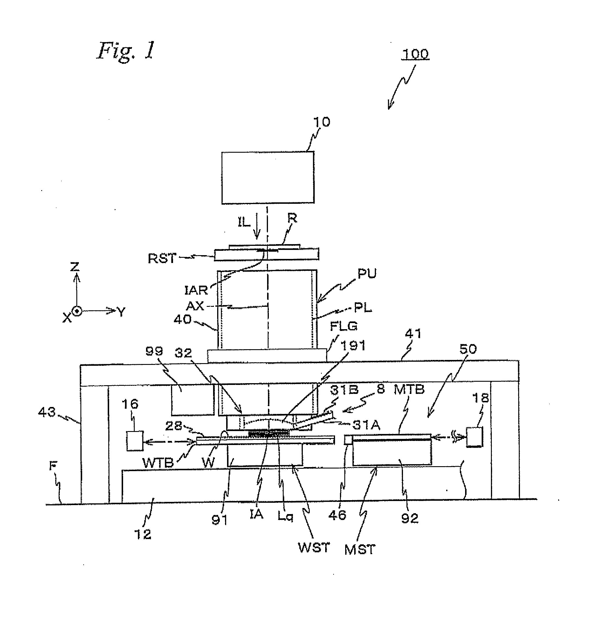
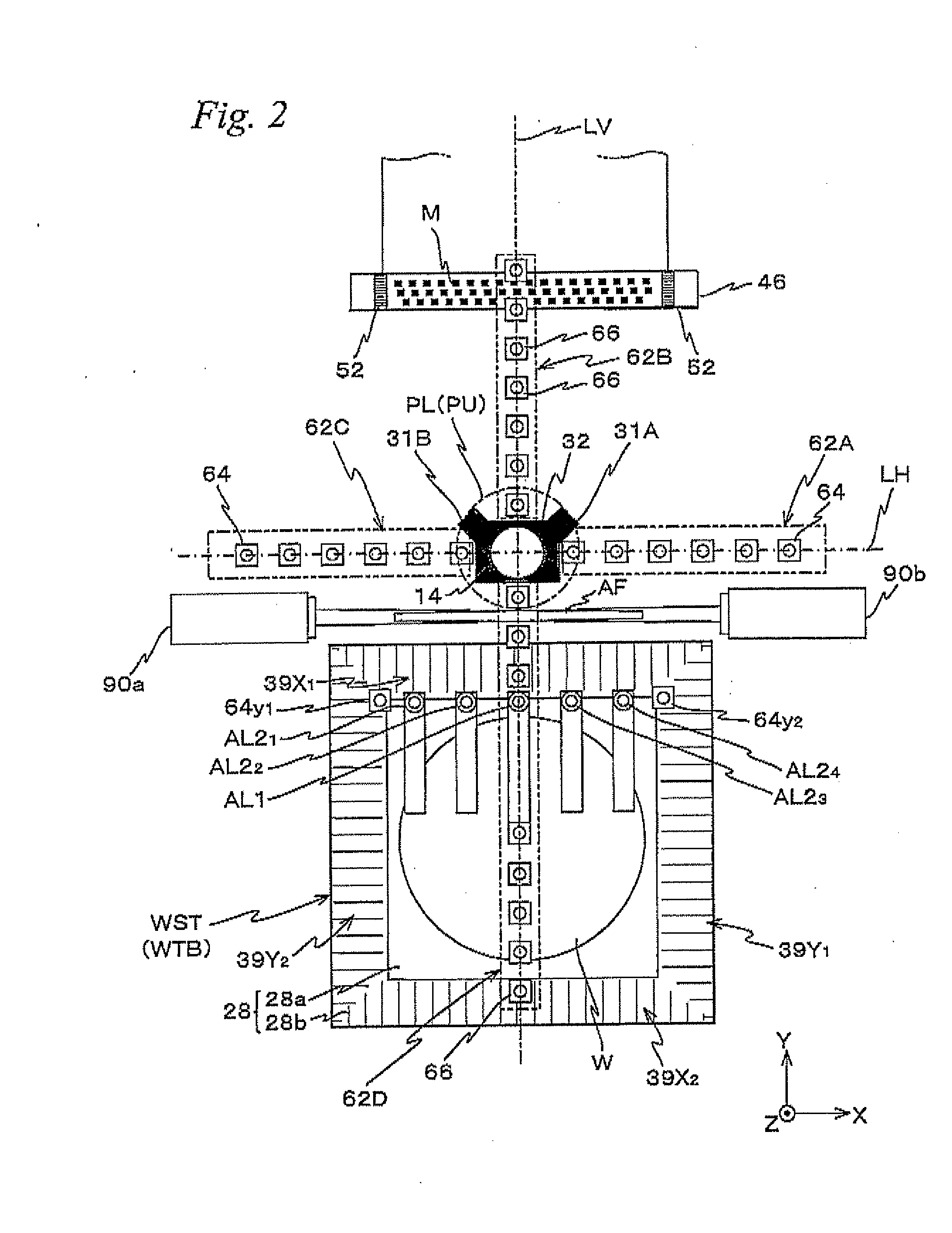
[0048]An embodiment of the present invention will be described below, with reference to FIGS. 1 to 14C.

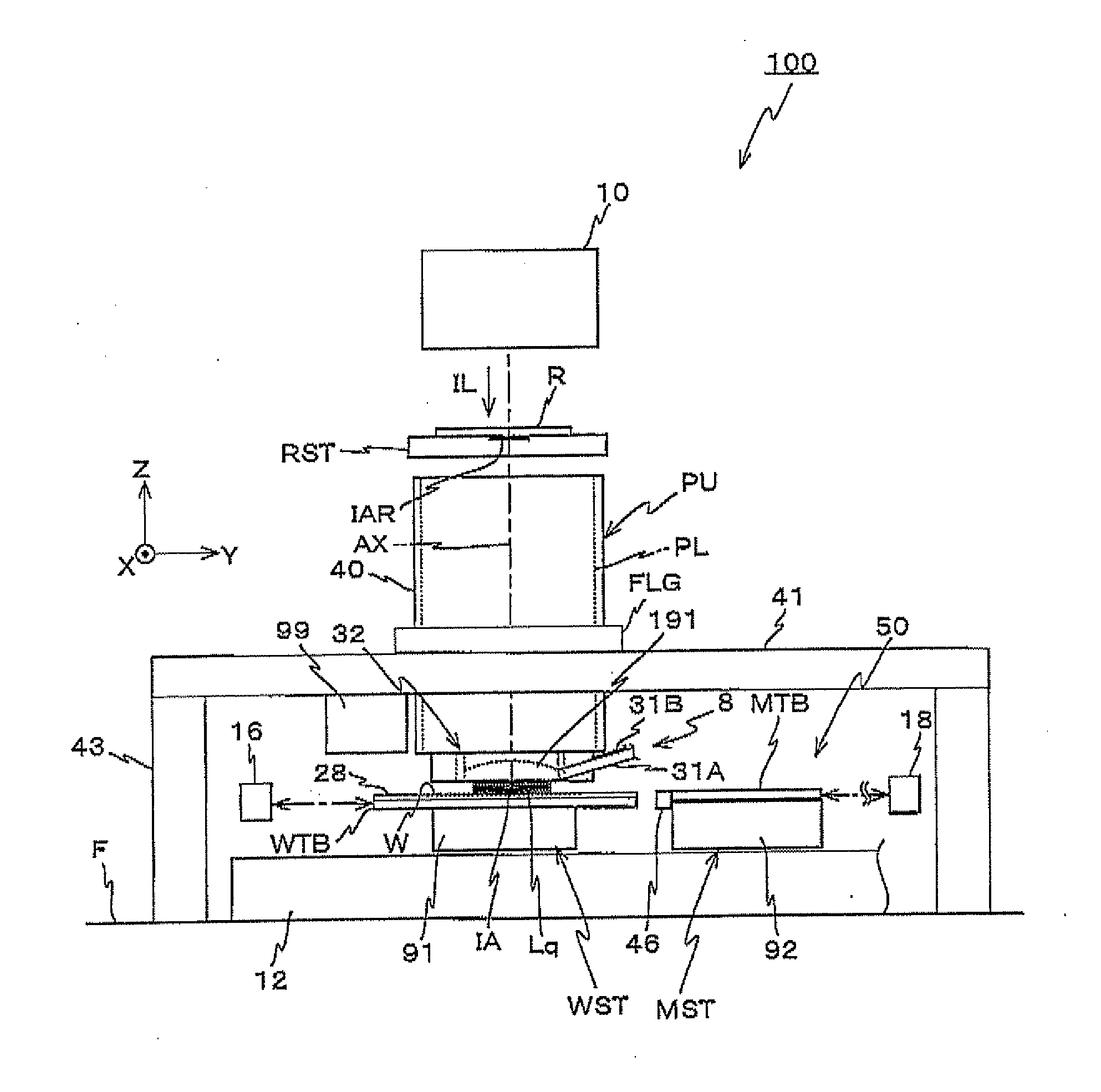
[0049]FIG. 1 shows a schematic configuration of an exposure apparatus 100 related to the embodiment. Exposure apparatus 100 is a projection exposure apparatus of the step-and-scan method, namely the so-called scanner. As it will be described later, a projection optical system PL is arranged in the embodiment, and in the description below, a direction parallel to an optical axis AX of projection optical system PL will be described as the Z-axis direction, a direction within a plane orthogonal to the Z-axis direction in which a reticle and a wafer are relatively scanned will be described as the Y-axis direction, a direction orthogonal to the Z-axis and the Y-axis will be described as the X-axis direction, and rotational (inclination) directions around the X-axis, the Y-axis, and the Z-axis will be described as θx, θy, and θz directions, respectively.

[0050]Exposure apparatus 100 inclu...


PUM


Abstract

By a force generation device which can generate a magnetic attraction and gas static pressure between a detection system provided on a lower surface side of an FIA surface plate and a surface plate, a predetermined clearance is formed between the detection system and the surface plate, and in a state where the clearance is formed (a floating state), the detection system is driven by a drive device in at least an uniaxial direction within a horizontal plane. Therefore, because the detection system is in a non-contact state to the base platform, movement (positioning) of the detection system with high precision becomes possible. Further, by setting an attraction larger than a repulsion generated by the force generation device, the detection system can be fixed (landed) in a state positioned with high precision.

Description

CROSS-REFERENCE TO RELATED APPLICATIONS[0001]This is a continuation of International Application PCT / JP2007 / 071702, with an international filing date of Nov. 8, 2007, the disclosure of which is hereby incorporated herein by reference in its entirety, which was not published in English.BACKGROUND OF THE INVENTION[0002]1. Field of the Invention[0003]The present invention relates to holding apparatus, position detection apparatus and exposure apparatus, moving methods, position detection methods, exposure methods, adjustment methods of detection systems, and device manufacturing methods, and more particularly to a holding apparatus which movably holds a detection system detecting a mark on an object, a position detection apparatus equipped with a detection system which detects a mark on an object and an exposure apparatus equipped with the position detection apparatus, a moving method to move a detection system which detects a mark on an object, a position detection method using the mo...

Claims


Application Information

Patent Timeline
IPC IPC(8): G03F7/20G01B11/00G03B27/58G03B27/32H01F7/04
CPCG03F7/7085G03F7/70816G03F7/70716G03F7/70825G03F9/7073G03F9/708G03F9/7088
Inventor SHIBAZAKI, YUICHI
Owner NIKON CORP
Learn More