Multi-Channel Optical Communication

a multi-channel optical communication and optical communication technology, applied in multiplex communication, data switching networks, instruments, etc., can solve the problems of complex design and manufacture, time-consuming, logistical difficulties, etc., and achieve the effect of maximizing system/laser bandwidth

Inactive Publication Date: 2009-09-17
EMCORE INC
View PDF12 Cites 12 Cited by
  • Summary
  • Abstract
  • Description
  • Claims
  • Application Information

AI Technical Summary

Benefits of technology

[0053]When the system / laser bandwidth is maximized, fiber strands coming from other cards can be combined together using CWDM or DWDM techniques. This is used in order to create a larger multi-channel solution over a single fiber. The entire system is preferably managed by an optional SNMP Ethernet-based protocol.
[0054]In a particularly preferred mode of the method of configuration of the device, each produced system can be individually configured by the user / designer on-line. This user customization to provide for user-selected individual communications types and related required protocols is heretofore unachievable for such a complex system with so many components that may interface with one another. However, using the system of base component cards customizable to any type of user required protocol and an interface of proprietary software allows the configuration of a system tailored specifically to a client's needs, and the device may be actually designed by the buyer or user on-line and then produced.

Problems solved by technology

Because each user at each transmission and reception site may be employing any or all of the different electronic signals and protocols, it is a complex task to design and manufacture site-specific data transmission systems that will communicate with remote sites and which may be required to accommodate the same or other types of electronic data signals and associated protocols.
Such differing types of data stream transmission and reception requirements (even between two remote locations of the same company or government department) can create logistical difficulties.
Furthermore, designing a data transmission and reception system which will suit each customer's individualized needs can be complex and time consuming.
Further complications arise when signals originate over an Ethernet or satellite network, and must be converted to transmission over a fiber optic network for communication to the remote destination.

Method used


Image

  • Multi-Channel Optical Communication
  • Multi-Channel Optical Communication
  • Multi-Channel Optical Communication

Examples


Embodiment Construction

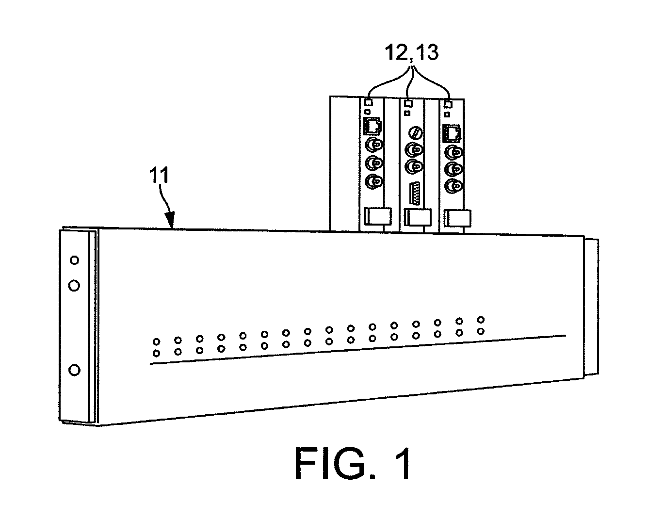
[0068]FIGS. 1-7 show some preferred embodiments and operational modes of the present invention, and a modular configuration providing for user configuration of fiber optic data transmission system and production thereof based on user or buyer input to configure the modular cards 12 on which the system is based.

[0069]As shown in FIG. 1 an optical transition system constructed in accordance with the invention comprises a housing 11 which houses a motherboard (not shown) connected to a bus (not shown). The bus is further connected to a plurality of slots (not shown), each of which can receive a modular card 12 / 13 to be described below.

[0070]As depicted in FIG. 2, common cards 12, 13 are provided and are adaptable for multiple configurations with components and operating instructions to drive the chosen components for that card. The common cards may be configured as a modular card 12 or as an optical card 13, the difference between the modular card 12 and the optical card 13 being that ...


PUM


Abstract

An optical fiber communications apparatus comprises a housing provided with a motherboard and with a support defining plurality of card receptors. A plurality of modular cards (12, 13) are provided, each of which is engageable with the motherboard via one of the card receptors. A optical card (12) includes an optical transceiver (20) for communication using a digital, optical communications signal over a single optical fiber link (17). Each modular card (12, 13) is provided with a plurality of circuit sub-assemblies (16), each circuit sub-assembly being configured for digital communication with a respective local audio, video or data electronic device via a respective connector using a respective electronic information-carrying signal. Each circuit sub-assembly (16) is configured for communication of an audio, video or data information-carrying signal with the transceiver using the digital, optical communications signal. A processor having operating instructions is provided for ascertaining the number of modular cards engaged with the motherboard and the number of circuit sub-assemblies on each of the modular cards, and for assigning time slots for the individual information-carrying signals of the circuit sub-assemblies, thereby controlling transmission of communications between the optical transceiver and the circuit sub-assemblies, and time division multiplexing those communications over the single optical fiber link to communicate a predetermined combination of audio, video and data channels multiplexed onto a single optical channel carried by the optical fiber link. A further aspect of the invention relates to controlling the power of a signal RF input into a light source used for optical communication. The power may be regulated according to a determined noise and/or distortion of a signal RF input to the amplifier or may be varied so that it lies in a predetermined range.

Description

FIELD OF THE INVENTION[0001]The field of the invention relates to communication systems and more particularly to optical communication systems.BACKGROUND OF THE INVENTION[0002]The invention relates to an apparatus and a method for transmission of data over a network, and from point to point. More particularly, it relates to an apparatus and method for configuring a multi-purpose optical transmitter or transceiver for communication of video, audio, and data signals, each with differing protocols, on a fiber optic network capable of utilizing a single optical fiber to communicate any of the differing types of signals and protocols associated with it. Further, a software program is provided to allow users to configure or customize the system using menu-driven graphical interface screens and common configurable components.[0003]With the ever-widening reach of public and private data networks used by the public, and especially by business and government, there continues to be an increase...

Claims


Application Information

Patent Timeline
Patent Type & Authority Applications(United States)
IPC IPC(8): H04J14/08
CPCG02B6/4453
Inventor DEGAN, ALONSATHER, FRED
Owner EMCORE INC
Why Eureka
Try Eureka