Power supply unit
- Summary
- Abstract
- Description
- Claims
- Application Information
AI Technical Summary
Benefits of technology
Problems solved by technology
Method used
Image
Examples
embodiment 1
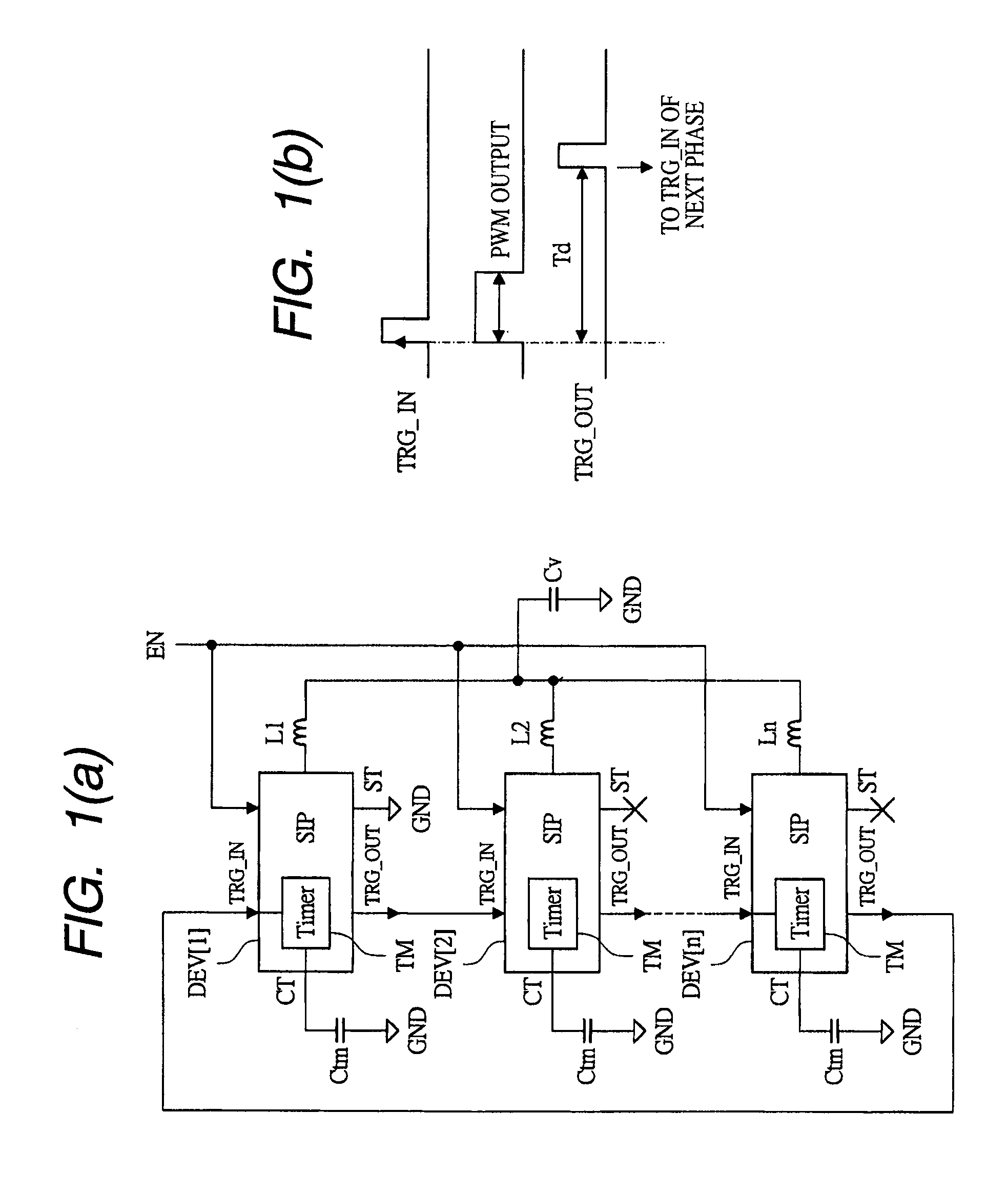
[0032]FIGS. 1(a) and 1(b) show a basic concept of a power supply unit according to Embodiment 1 of the present invention, wherein FIG. 1(a) is a schematic diagram showing a configuration example thereof, and FIG. 1(b) is an explanatory view showing an operation example of FIG. 1(a). The power supply unit shown in FIG. 1(a) has a configuration for realizing a multiphase power supply of n (n>=2) phases, and comprises n semiconductor devices (or semiconductor ICs) DEV[1]-DEV[n], n inductors L1-Ln, an output capacitor Cv, and the like.
[0033]Each of DEV[1]-DEV[n] comprises a trigger input terminal TRG_IN, a trigger output terminal TRG_OUT, and a timer circuit TM. TM receives a signal of TRG_IN as an input, and delays it based on a capacitor Ctm coupled to a delay time setting terminal CT, and outputs the delayed signal from TRG_OUT. Note that, an analog delay based on the capacitor Ctm is used here, but not limited thereto, and this can be replaced with various kinds of generic delay cir...
embodiment 2
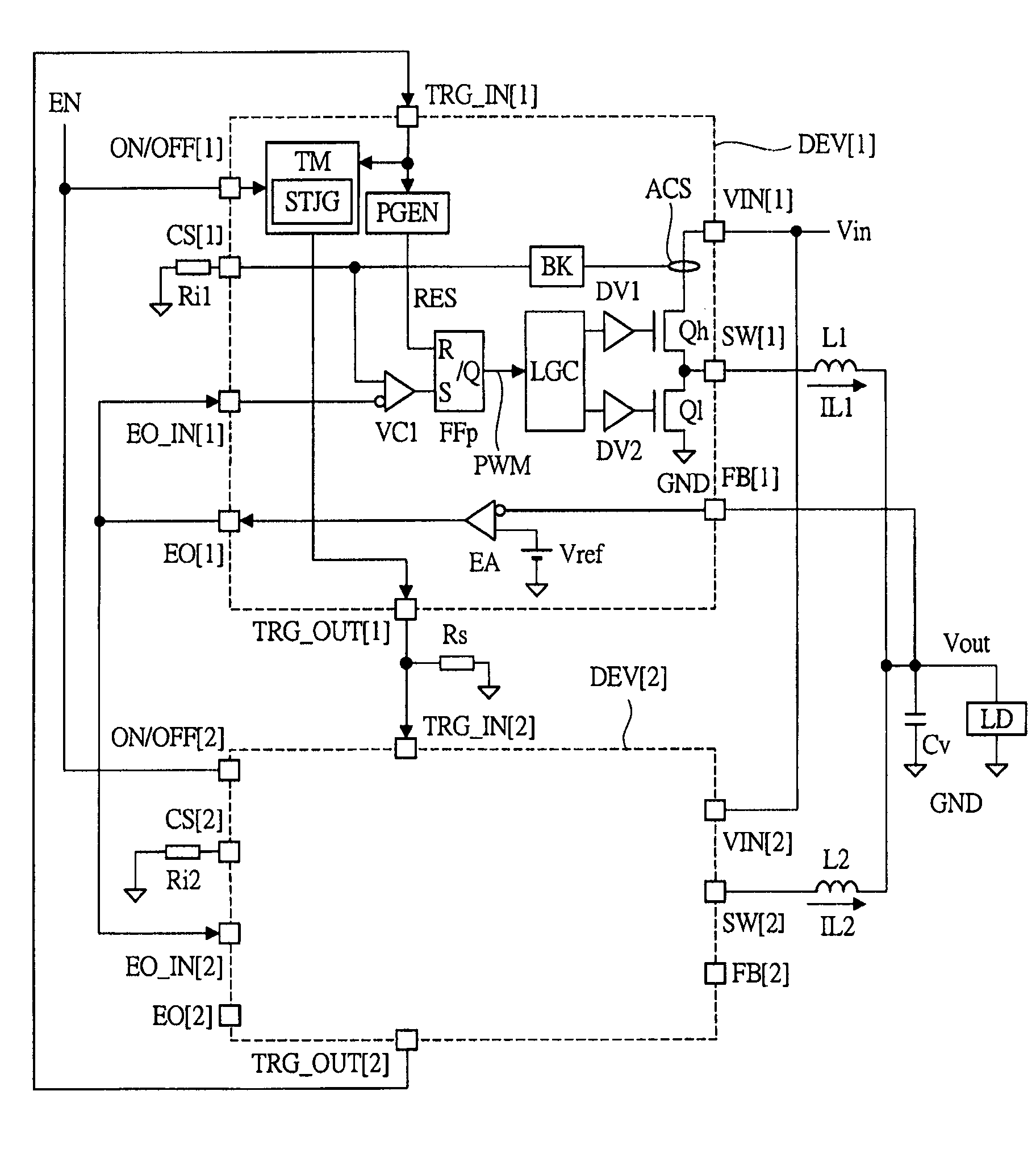
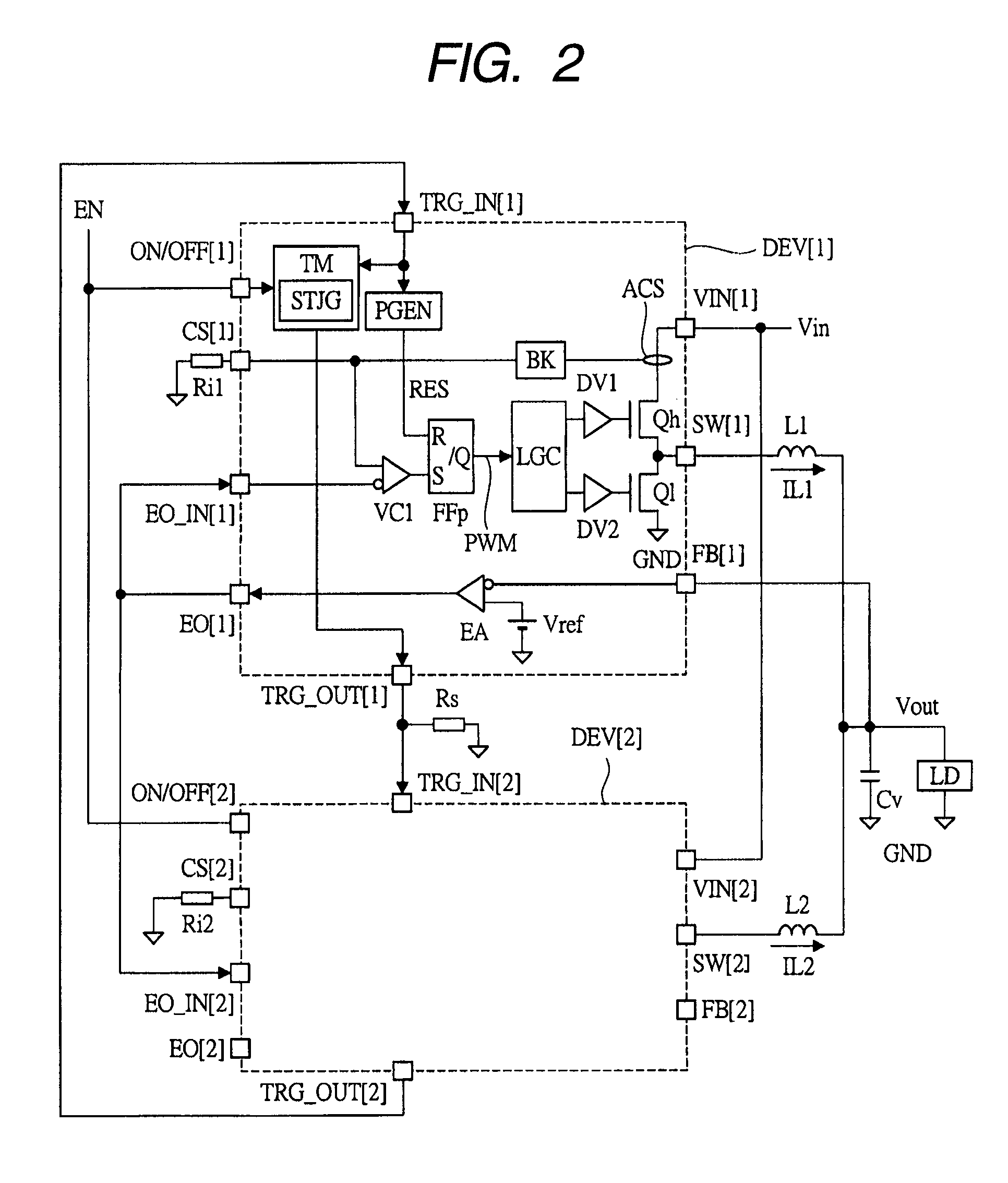
[0052]In Embodiment 2, a more detailed configuration example of the semiconductor device DEV described in Embodiment 1 is described. FIG. 4 is a block diagram showing a detailed configuration example of a semiconductor device used in a power supply unit according to Embodiment 2 of the present invention. FIG. 5 is a plan view showing an example of the package form of the semiconductor device of FIG. 4. The configuration example shown in FIG. 4 is a further embodied one of the configuration example of FIG. 2 described above, and the general configuration and operation thereof are the same as those of FIG. 2 and FIG. 3. Here, the description is made paying attention to the portions further embodied from the configuration example of FIG. 2.
[0053]The semiconductor device (or a semiconductor IC) DEV shown in FIG. 4 basically comprises the transistor Qh serving as a high side transistor (e.g., MOSFET), the transistor Ql serving as a low side transistor (e.g., MOSFET), and various control ...
embodiment 3
[0088]In Embodiment 3, an example is described, in which a single phase power supply is realized using the semiconductor device DEV described in Embodiment 2 (FIG. 4 or the like). FIG. 9 is a wiring diagram showing a configuration example in a power supply unit according to Embodiment 3 of the present invention. To the semiconductor device DEV[1] shown in FIG. 9, the same external resistors and external capacitors as those of DEV of FIG. 4 or DEV[1] of FIG. 6 are coupled. The difference is that the trigger output terminal TRG_OUT of DEV[1] is coupled to its own trigger input terminal TRG_IN, and the external resistor Rs is coupled to this TRG_OUT. Other than this, the configuration is the same as that of DEV of FIG. 4, or DEV[1] of FIG. 6, so the detailed description thereof is omitted.
[0089]Since the semiconductor device DEV described in FIG. 4 or the like does not require a master IC as in the prior art and shows a configuration example capable of operating by itself, it can opera...
PUM
 Abstract
Description
Claims
Application Information
 - R&D
- Intellectual Property
- Life Sciences
- Materials
- Tech Scout
- Unparalleled Data Quality
- Higher Quality Content
- 60% Fewer Hallucinations
Browse by: Latest US Patents, China's latest patents, Technical Efficacy Thesaurus, Application Domain, Technology Topic, Popular Technical Reports.
© 2025 PatSnap. All rights reserved.Legal|Privacy policy|Modern Slavery Act Transparency Statement|Sitemap|About US| Contact US: help@patsnap.com


