
Safety and indicator apparatus systems and methods for high pressure conduits

a safety and indicator apparatus and high-pressure conduit technology, applied in the direction of hose connection, mechanical apparatus, pipe protection against damage/wear, etc., can solve the problems of hose burst, pin-hole leakage, leakage and failure, severe tissue damage and burns, etc., to achieve simple manufacture and implementation, add stability and/or security, and the effect of simple structur

Active Publication Date: 2009-09-10
THE GATES CORP
View PDF12 Cites 35 Cited by
  • Summary
  • Abstract
  • Description
  • Claims
  • Application Information

AI Technical Summary

Benefits of technology

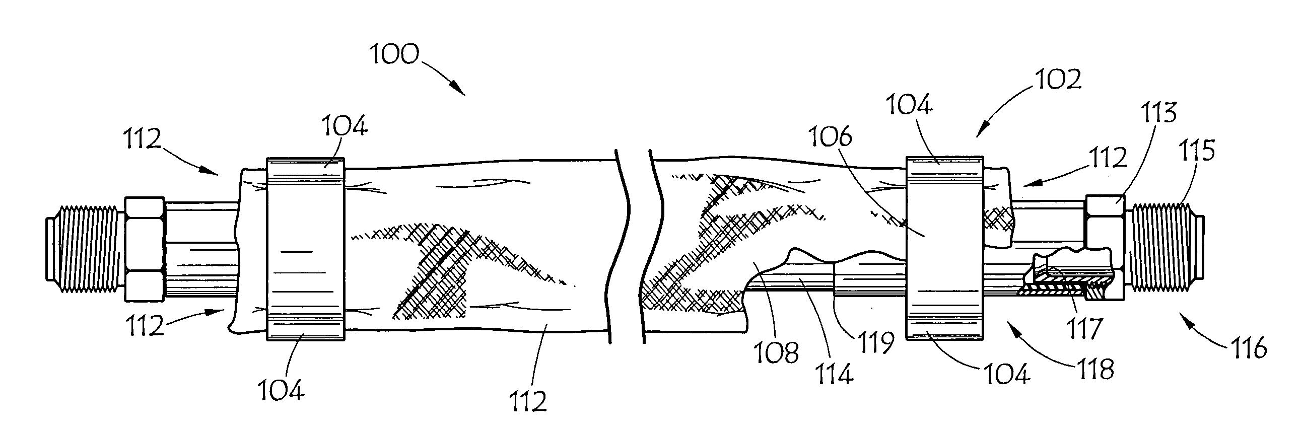
[0012]It would be beneficial to contain any and all material from a hose burst or pin-hole failure so that a person standing nearby would be entirely protected from danger. A hose can unpredictably burst or develop a pin-hole at any location along its length, making protection very challenging. Therefore, it would be beneficial to provide a safety assembly for a hydraulic conduit in which the securement of the encompassing sleeve or encasement is reliable and fixed. However, it would not only be of benefit to shield the hose assembly, but also to reduce pressure build up behind a protective outer hose sleeve to avoid accumulation of material and eventual failure of the sleeve.
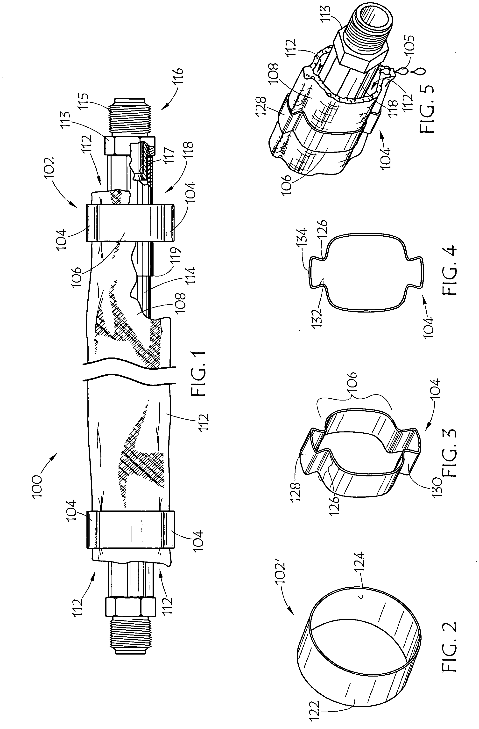
[0013]Whereas there is no provision in the currently available hose protection systems for relieving pressure of fluid that has escaped from a hydraulic hose and builds up behind an encasement surrounding the hose, no protection exists against the imminent burst of the encasement itself and the ensuing high pressure and / or high temperature stream of fluid. The present pressure relief assembly provides pressure relief for escaped fluid from a high pressure conduit such that the escaped fluid hits a sleeve that surrounds the conduit, slows in velocity, and drains toward one or both ends of the conduit, via a channel, preferably provided by a collar. The escaping fluid does not have opportunity to accumulate behind the sleeve, build in pressure, burst through the protective sleeve and pose danger to the operator standing next to the conduit. Rather, the fluid from a pin-hole, or contained burst, drains out of the sleeve at the end portion(s) of the conduit, which in turn alerts the operator to the failure of the conduit.
[0015]Any type of compression method can be used to secure the collar to the sleeve. For example, if using a crimping tool, dies having a tapered generally trapezoidal shape in cross-section, may be retracted to produce the raised portion(s). Upon compression of the collar, the “flowing” metal, which follows the shape of the dies' contact surfaces, forms raised portions. Therefore the shape, size, or cross-section of the raised portion is easily variable depending upon the desired use of the present invention. Additional collars could be used, or collars could be attached to one another or “stacked” in an adjacent fashion along certain portions of the length of the hydraulic conduit for additional stability and / or security.
[0016]An important advantage of the various embodiments of the present invention is that the sleeve is held in place securely, yet just enough of a channel is provided by the raised portion(s) of the ferrule through which fluid from a hose failure can flow. The various embodiments of the present invention are low-cost, simple to manufacture and implement at time of manufacture or as a retrofit, and are lightweight, elegant, and effective.
[0018]It would therefore be of benefit to provide a system that would decrease the velocity and pressure of the escaping fluid and provide a safe channel through which the escaped fluid could flow. It would also be highly desirable to provide a system that would alert the operator to dangerous fluid escape from the conduit.
[0020]Another advantage afforded by embodiments of the present invention is that when failure in a hose is close to the end of the sleeve, the force behind the fluid tends to pull yarn out of the woven matrix of the sleeve material. Thus, sleeve fabric unsupported by the collar tends to fail at the edge. In accordance with embodiments of the present invention, the end of the fabric making up the hose sleeve is supported and such “pull-out” is avoided.

Problems solved by technology

As is well known within the hydraulics industry, injury resulting from hose bursts and pin-hole leaks can occur in a matter of milliseconds.
Hydraulic systems may operate at very high pressures and a leak of pressurized fluid can penetrate the skin, causing severe tissue damage and burns.
Hydraulic hoses, especially those found on construction equipment, tractors and other equipment, are exposed and therefore vulnerable to wear, which can result in leakage and failure.
While a protective encasement, or sleeve, can help reduce wear of a hydraulic hose due to abrasion, a sleeve on its own does not prevent high pressure streams from bursting through the sleeve itself.
In the past, problems that have affected the design of such systems have included hose pin hole streams or bursts as well as whipping, where an unmitigated flow of fluid from the end of a hose causes uncontrolled movement of the hose and hose end, posing great danger to an operator.
Under high operating pressures or heavy weight, the hose and / or fitting can come loose or blow off the hose, causing the end of the hose to whip with great force.
These sleeves somewhat help to protect hose from wear and may prolong the life of the hose.
These currently available high pressure conduit protection methods and systems do not protect against pressure build up of the escaped fluid behind the encasements.
The resulting damage to the encasement and / or subsequent release of a high pressure stream and or mist of dangerous fluid renders the encasement virtually useless for protection to operators or bystanders.
This is a dangerous situation because should the sleeve become detached from the conduit, the operator would be directly exposed to conduit failure.
Also, these methods of hose protections are bulky and highly reduce the flexibility of the hose assembly.
In the case of metal enclosures, their bulk and inflexibly render their use impractical in certain applications requiring flexible connection.
However, inhalation of certain fluids in the form of a spray or mist may be detrimental to one's health.
Further, when the material carried by the hose is at a very high temperature or when the wire sheath suffers wear and / or fails to carry out its intended duty, danger arises without warning.
Currently available flexible textile systems that attempt to provide such protection fail to meet these requirements, resulting in the potential for serious injury to operators, or even loss of life when unrestricted high pressure material bursts through any existing protective flexible textile encasement.
A hose can unpredictably burst or develop a pin-hole at any location along its length, making protection very challenging.
Whereas there is no provision in the currently available hose protection systems for relieving pressure of fluid that has escaped from a hydraulic hose and builds up behind an encasement surrounding the hose, no protection exists against the imminent burst of the encasement itself and the ensuing high pressure and / or high temperature stream of fluid.
The escaping fluid does not have opportunity to accumulate behind the sleeve, build in pressure, burst through the protective sleeve and pose danger to the operator standing next to the conduit.
Thus, sleeve fabric unsupported by the collar tends to fail at the edge.

Method used


Image

  • Safety and indicator apparatus systems and methods for high pressure conduits
  • Safety and indicator apparatus systems and methods for high pressure conduits

Examples


Embodiment Construction

[0028]Referring to FIGS. 1 and 5, embodiment 100 of the present safety and indicator apparatus and system is shown. In various embodiments of the present invention, the high pressure conduit may comprise hydraulic fluid conduits, such as hydraulic hose, line or pipe. However, it should be understood that the present assemblies can be used in conjunction with conduits or bundles of conduits of virtually any type or size including conduits in the farming, heavy duty equipment, aerospace, power, medical, oil, automotive, and other industries. In other various embodiments of the present invention, high pressure fluid in the form of a liquid may be carried by high pressure conduits employing the present invention. However, it should be understood that the present assemblies can be applied to conduits carrying any type of material, including high pressure hydraulic fluids such as synthetic compounds, mineral oil, water and water-based mixtures, or any other material.

[0029]Referring back t...


PUM


Abstract

A pressure-relieving safety assembly, comprising a sleeve and collar, protects against human injury and loss of life by blocking flow of fluid from a ruptured high pressure conduit and provides pressure relief for escaping fluid. This pressure-relieving assembly includes a sleeve that encircles the high-pressure line and is secured to, at one or both ends of the line, a coupling. The sleeve is secured to the coupling(s) by a collar having raised portions that provides a path for fluid that has escaped from the conduit at a burst or pin-hole failure location, to flow towards the ends of the conduit, indicating to the user that a conduit failure has occurred. The sleeve lowers the fluid velocity while the path provided by the collar prevents the fluid pressure from building up behind the sleeve.

Description

CROSS-REFERENCE TO RELATED APPLICATION[0001]This application claims the benefit of U.S. Provisional Application No. 61 / 068,538, of the same title, filed Mar. 7, 2008, which is incorporated herein by reference.BACKGROUND OF THE INVENTION[0002]1. Field of the Invention[0003]This invention relates generally to pressurized conduits such as hoses and tubes, more particularly to systems and methods for protecting against human injury and loss of life due to catastrophic failures in the form of bursts or pin-hole failures in such high pressure fluid conduits, and specifically to a sleeve and collar safety assembly that encloses the length of a high pressure conduit.[0004]2. Description of the Prior Art[0005]As is well known within the hydraulics industry, injury resulting from hose bursts and pin-hole leaks can occur in a matter of milliseconds. Hydraulic systems may operate at very high pressures and a leak of pressurized fluid can penetrate the skin, causing severe tissue damage and burn...

Claims


Application Information

Patent Timeline
IPC IPC(8): F16L11/00
CPCF16L13/148F16L57/02F16L57/00F16L35/00F16L55/005
Inventor GRAY, YELENA
Owner THE GATES CORP
Learn More