
Reproduction method and hologram recording medium

a recording medium and hologram technology, applied in the field of hologram recording medium and reproduction method, can solve the problems of difficult detection of phase information by the apparatus, nonlinearity, and difficult detection of image sensor 104/b>, and achieve the effect of preventing the occurrence of damage to the recording layer (recording material) and the corruption of recording data

Inactive Publication Date: 2009-09-03
SONY CORP
View PDF2 Cites 4 Cited by
  • Summary
  • Abstract
  • Description
  • Claims
  • Application Information

AI Technical Summary

Benefits of technology

[0036]By performing reproduction through the coherent addition as described above, the following advantages can be obtained:
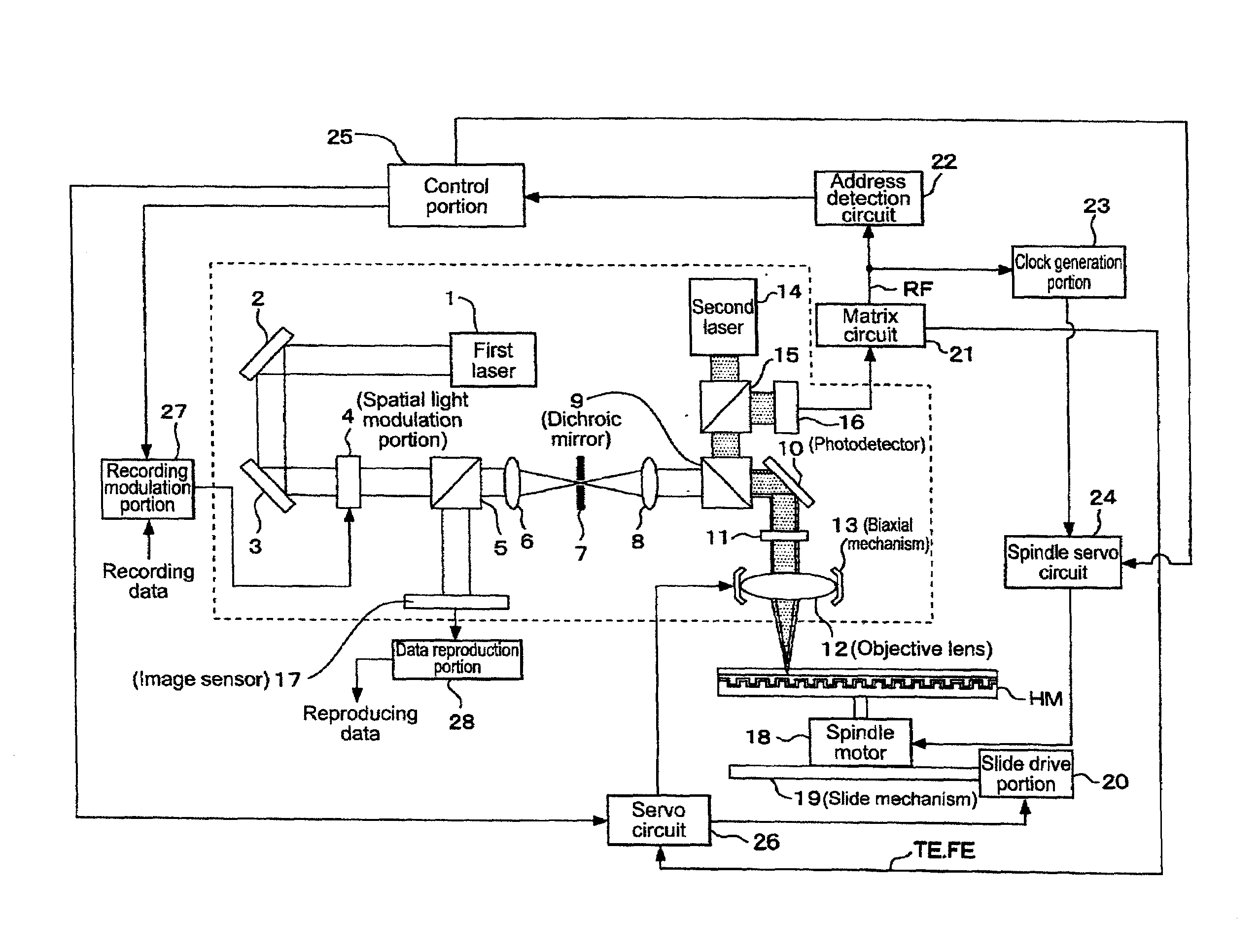
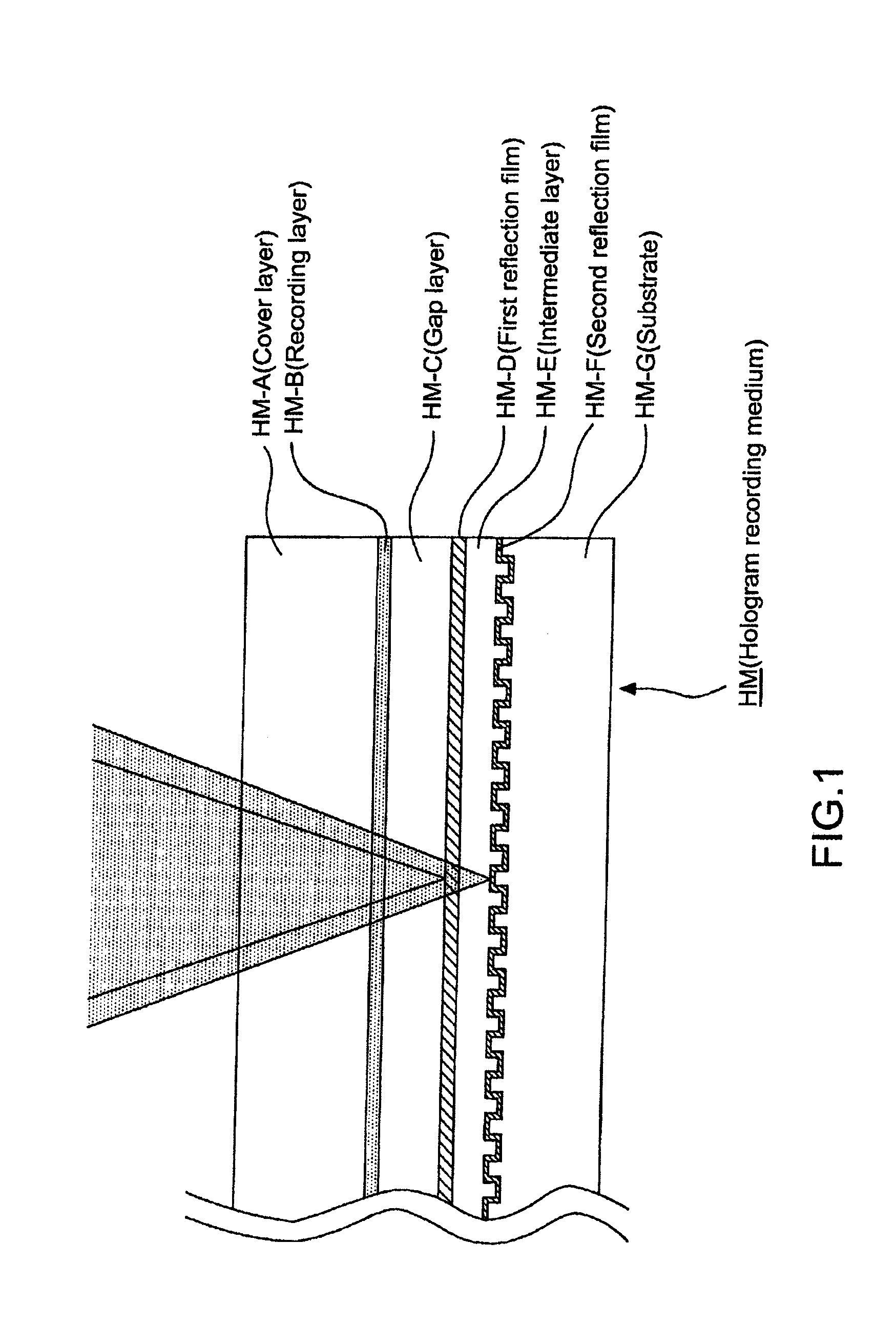
[0058]As described above, according to the present invention, the formation of the gap layer can set the focus point of the irradiation light and the recording layer apart from each other. In other words, it is possible to perform defocusing in an amount corresponding to the thickness of the gap layer. With this structure, in the case of performing reproduction from the hologram recording medium through irradiation of the reference light and the coherent light with the coherent addition, the peak intensity of the light spot due to the coherent light can be effectively suppressed, and corruption of the recording data and occurrence of damage to the recording layer (recording material) can be prevented.

Problems solved by technology

In contrast, however, it is difficult for the image sensor 104 to detect the phase information recorded on the hologram recording medium 100.
As described above, in a hologram recording / reproducing system, a medium thereof can record the phase information, but the phase information is difficult to be detected by an apparatus thereof.
Thus, nonlinearity is caused in this point.

Method used


Image

  • Reproduction method and hologram recording medium
  • Reproduction method and hologram recording medium
  • Reproduction method and hologram recording medium

Examples


modified example

[0245]The embodiment of the present invention is described above, but the present invention is not limited to the examples described above.

[0246]For example, the case where the recording track is formed along with the formation of the pit rows on the substrate HM-G is described above. Alternatively, the track may be formed with a groove (groove continuously formed). In this case, the address information and the clock information can be recorded using information on a cycle of meandering of the groove.

[0247]Alternatively, it is also possible to provide the groove with only a function of guiding the recording position of the hologram page without meandering, and additionally form a pit row for recording the address information and the clock information with the pit row and the groove being traveled side by side. In this case, an optical system is structured as follows: irradiation with the second laser light is performed so that at least two laser spots used for detecting the tracking...


PUM


Abstract

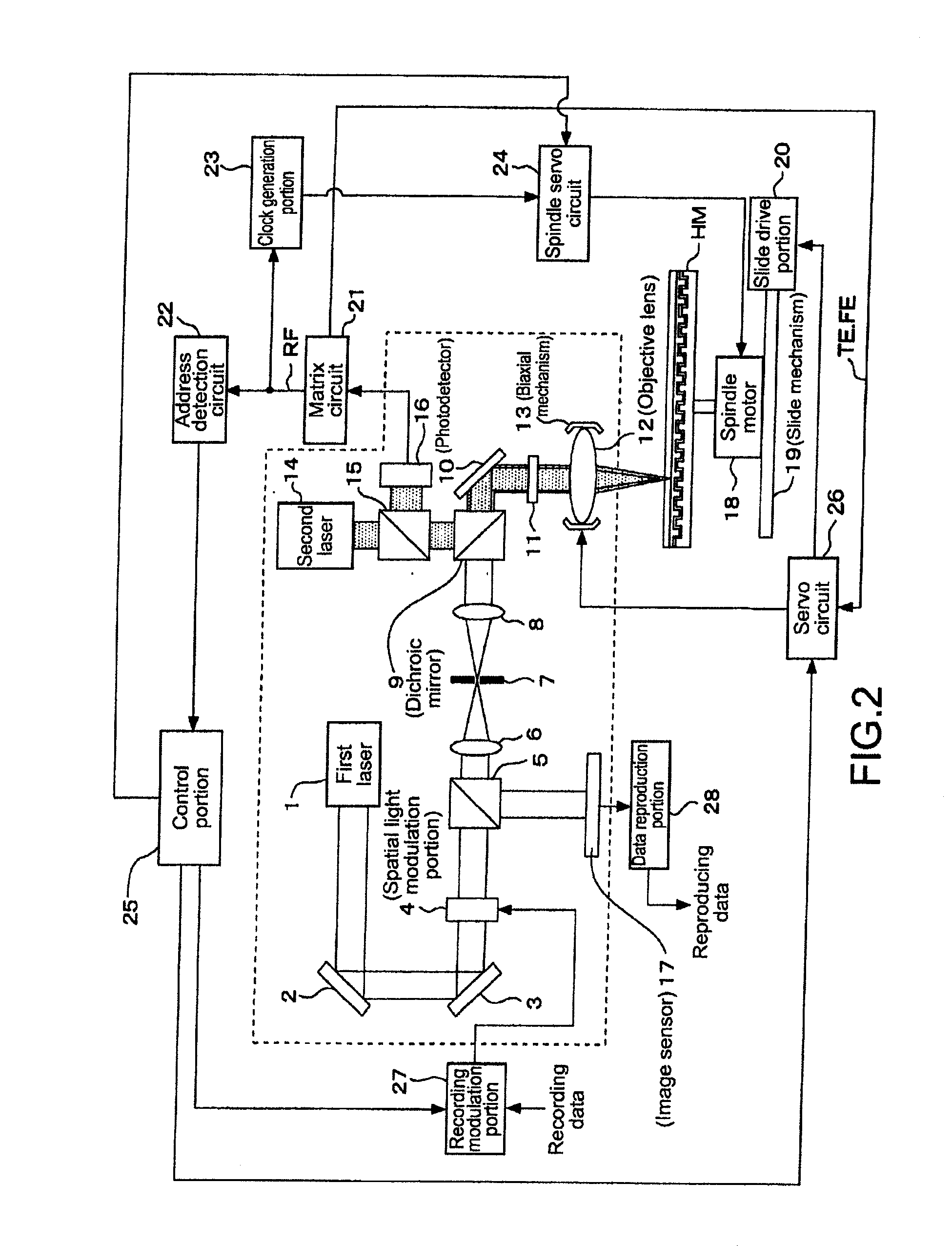
Disclosed is a reproduction method for a hologram recording medium on which information is recorded with interference fringes of signal light and reference light, including: generating, based on light from a first light source, the reference light and coherent light caused to have uniform amplitude and phase, and irradiating the hologram recording medium with the reference light and the coherent light, the hologram recording medium including a recording layer on which the information is recorded with the interference fringes of the signal light and the reference light, a first reflection film formed on a lower surface side of the recording layer, and a gap layer formed between the recording layer and the first reflection film; and receiving the coherent light and a reproduction image that corresponds to recording information and is obtained as reflection light from the hologram recording medium through light irradiation in the light irradiation step, and reproducing the information based on a result of the light received.

Description

CROSS REFERENCES TO RELATED APPLICATIONS[0001]The present invention contains subject matter related to Japanese Patent Application JP 2008-048039 filed in the Japanese Patent Office on Feb. 28, 2008, the entire contents of which being incorporated herein by reference.BACKGROUND OF THE INVENTION [0002]1. Field of the Invention[0003]The present invention relates to a reproduction method for a hologram recording medium on which data is recorded with interference fringes of reference light and signal light, and a hologram recording medium.[0004]2. Description of the Related Art[0005]As disclosed in Japanese Patent Application Laid-open No. 2006-107663 and Japanese Patent Application Laid-open No. 2007-79438 (hereinafter, referred to as Patent Documents 1 and 2, respectively), there is known a hologram recording / reproducing method in which data is recorded with interference fringes of signal light and reference light and the data recorded with the interference fringes is reproduced throu...

Claims


Application Information

Patent Timeline
IPC IPC(8): G11B7/00G03H1/04
CPCG03H1/02G03H2001/0224G03H2223/13G03H2225/31G11B7/24044G03H2225/55G11B7/0065G11B7/1275G11B7/128G03H2225/33
Inventor TANAKA, KENJIFUKUMOTO, ATSUSHIHARA, MASAAKI
Owner SONY CORP
Learn More